7 | Electrical installation Baumer
60 Operating Manual VCXG.2 / VCXG.2.XC / VCXG.2.I / VCXU.2 | V1.2
7 Electrical installation
7.1 General instructions for electric installation
NOTICE
Device damage due to faulty power supply.
The device can be damaged due to faulty power supply.
a) Operate the device only with protected low voltage and safe electrical isolation of protection
class III.
NOTICE
Device damage or unintended operation due to work on live parts.
Any wiring work on live parts may lead to unintentional operation.
a) Prior to performing any wiring work disconnect power supply.
b) Only connect or disconnect any terminals when not live.
7.2 VCXG.2
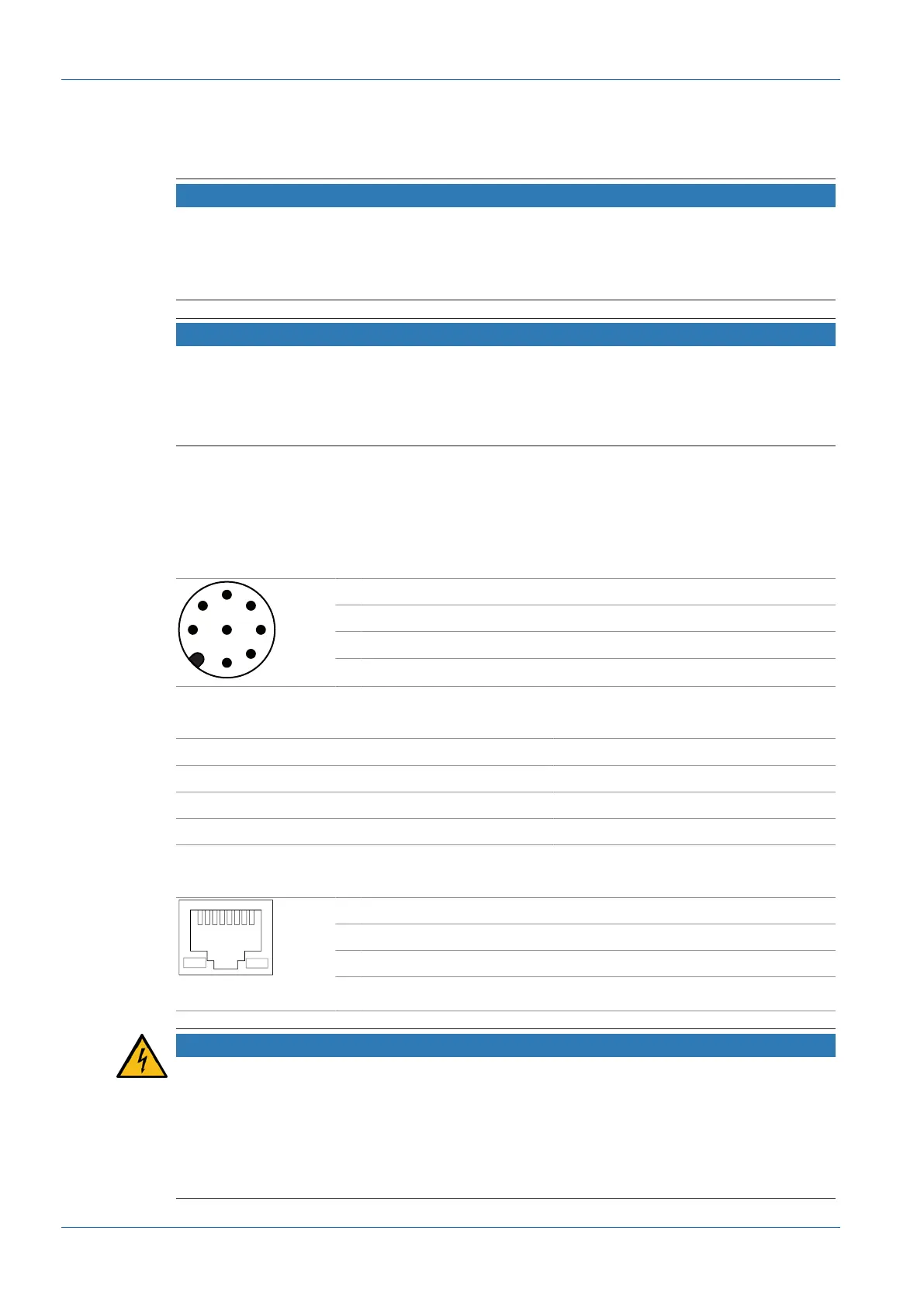
7.2.1 Pin assignment
Power supply / Digital IO
1 GPIO (Line2) 2 Power V
CC
(12 … 24 VDC ± 20%)
3 IN1 (Line0) 4 GND IN1
5 Power V
CC
(OUT1) 6 OUT1 (Line3)
7 GND (Power, GPIO) 8 GPIO (Line1)
Cable core colors (cable not included in delivery)
1 WH – White 2 BN – Brown
3 GN – Green 4 YE – Yellow
5 GY – Grey 6 PK – Pink
7 BU – Blue 8 RD – Red
Ethernet interface
1 MX1+ 2 MX1-
3 MX2+ 4 MX3+
5 MX3- 6 MX2-
7 MX4+ 8 MX4-
NOTICE
Power supply via PoE and digital IO connection
The camera supports power supply via PoE (Power over Ethernet) IEEE 802.3af Clause 33,
48V.
Parallel power supply via Ethernet interface and digital IO port is subject to deviations and toler-
ances. These might damage the camera.
a) Only use a single form of power supply!


 To Next Page