7 | Electrical installation Baumer
72 Operating Manual VCXG.2 / VCXG.2.XC / VCXG.2.I / VCXU.2 | V1.2
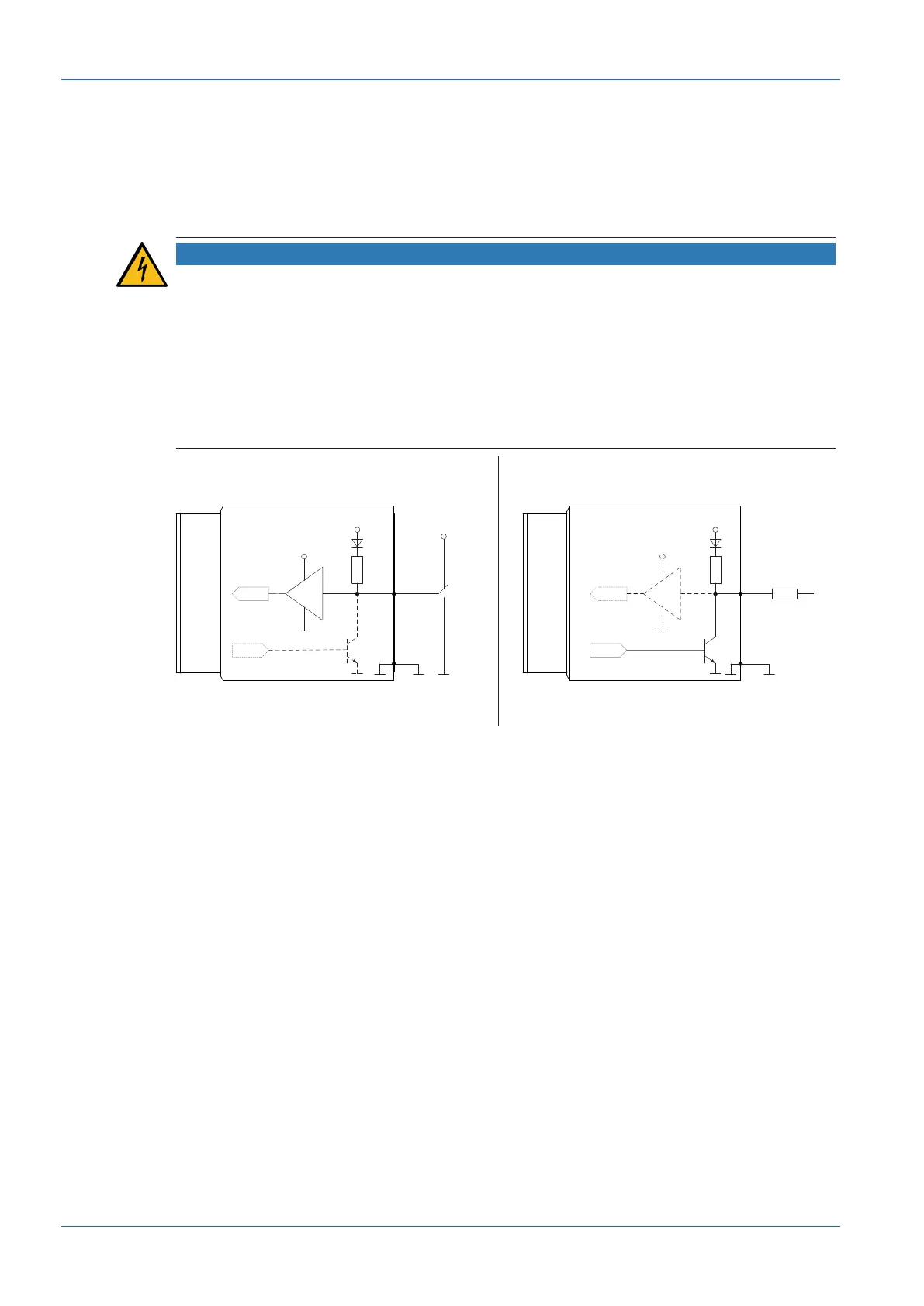
7.5.3 GPIO (General Purpose Input / Output)
Line1 and Line2 are GPIOs and can be both Input and Output.
Input: (0 ... .0.8 V low, 2.0 ... 30 V high).
Output:(0 ... .0.4 V low, 2.4 ... 3.3 V high), @ 1 mA load (high) / 50 mA sink (low)
NOTICE
Overvoltage, undervoltage or inverted polarity can result in defect!
General Purpose IOs (GPIOs) are not potential-free and do not feature overvoltage power off.
Incorrect wiring, overvoltage, undervoltage or reverse polarity can damage the electronics.
GPIO power supply VCC: 3.3 V DC
Load resistance for TTL high level: approx. 2.7 kΩ
GPIO configuration is by default an in the camera as Input. They have to assigned to
GPIO_GND if not used or configured as Output. Configuration as Output by default (saved in
User Set) is feasible.
Input
300
Output
Pin 1 / 8
3.3 V
3.3 V
FPGA
FPGA
FPGA
FPGA
Pin 7
Pin 1 / 8
Pin 7
Ω
300
Ω
High:
2.4 .. 3.3 V
I sink max.
= 50 mA
Low:
0 V .. 0.4 V
Low:
0 V .. 0.8 V
High:
2.0 V .. 30 V
GPIO GPIO
GND GPIO
GND GPIO