7 | Electrical installation Baumer
68 Operating Manual VCXG.2 / VCXG.2.XC / VCXG.2.I / VCXU.2 | V1.2
7.4 VCXG.2.I
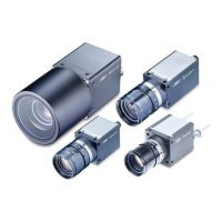
7.4.1 Pin assignment
Stromversorgung / Digital-IO
1 Power V
CC
(12 … 24 VDC ± 20%) 2 GND (Power)
3 IN1 (Line0) 4 OUT1 (Line4)
5 IN2 (Line1) 6 OUT2 (Line5)
7 OUT3 (Line6) 8 IN3 (Line2)
9 OUT4 (Line7) 10 IN4 (Line3)
11 GND (IO) 12 Power (IO)
Cable core colors (cable not included in delivery)
1 BN – Brown 2 BU – Blue
3 WH – White 4 GN – Green
5 PK – Pink 6 YE – Yellow
7 BK – Black 8 GY – Grey
9 RD – Red 10 VT – Violet
11 GY-PK – Grey Pink 12 RD-BU – Red Blue
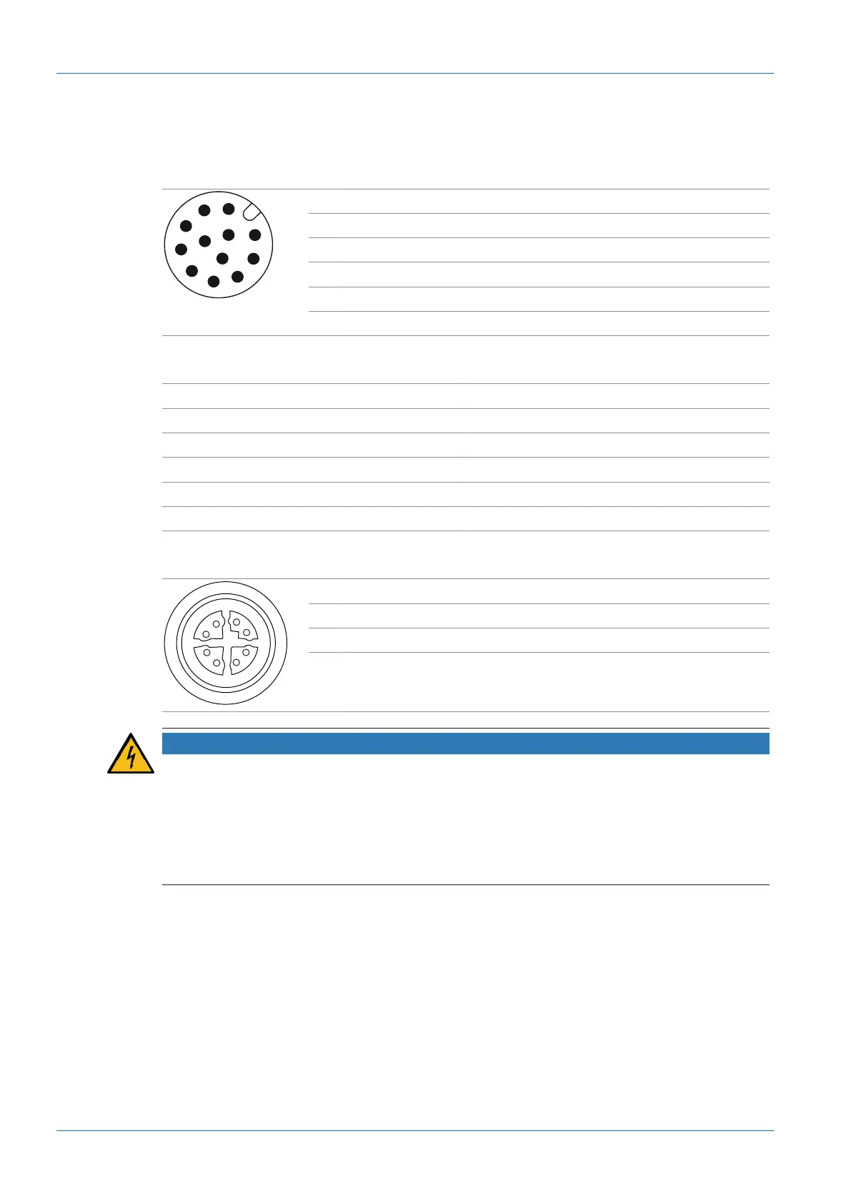
Ethernet interface
1 MX1+ 2 MX1-
3 MX2+ 4 MX2-
5 MX4+ 6 MX4-
7 MX3- 8 MX3+-
NOTICE
Power supply via PoE and digital IO connection
The camera supports power supply via PoE (Power over Ethernet) IEEE 802.3af Clause 33,
48V.
Parallel power supply via Ethernet interface and digital IO port is subject to deviations and toler-
ances. These might damage the camera.
a) Only use a single form of power supply!