Installation
Electrical Interface
DV14307.03 Issue 04 March 2016 Transceiver Family 620X 51
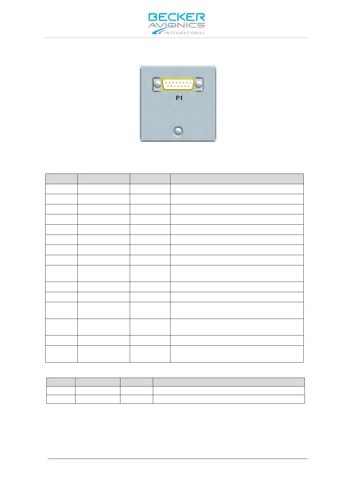
2.5.2. Connector and Pin Assignment (RCU6201)
Figure 2-16: Connector on rear plate of RCU6201
P1 Connector (System Interface)
The P1 connector (Figure 2-16) is a DSUB male connector with 15 pins and slide-in fastener.
Primary Control & Service Interface
Primary Control & Service Interface
Auxiliary Control Interface
Primary Control & Service Interface
Primary Control & Service Interface
Auxiliary Control Interface
P1-9 GND -
Power supply Ground (return), shielding for
RS422, Ground for discrete lines
Auxiliary Control Interface
Power supply Hot (positive)
P1-12 /SRV_EN OUT
ACTIVE state - closed contact to GND
P1-13 /EXT_ON IN
ACTIVE state - closed contact to GND
Auxiliary Control Interface
P1-15 /EXCH_CH IN
ACTIVE state - closed contact to GND
Panel Illumination
The RCU6201 controller push-buttons and LCD display can be illuminated. The illumination can be
configured in the configuration setup via front panel or externally via pin P1-6/P1-8 For external
configuration connect pin P1-6 to system ground and pin P1-8 to dimming voltage bus.