Installation
Wiring Diagrams and Settings
74 Transceiver Family 620X DV14307.03 Issue 04 March 2016
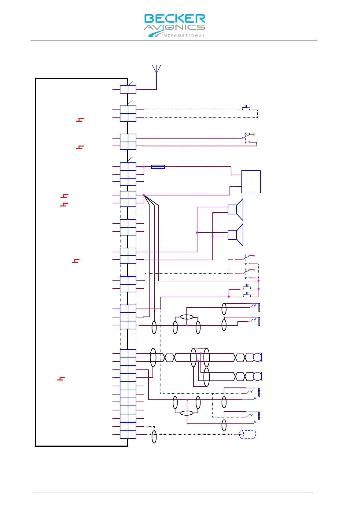
2.10.2.2. Wiring Diagram Twin Seat Motor Glider
J3
J1
P1
A
A
12 12
21 21
24
23
23
24
12 12
11 11
24 24
13 13
25 25
23 23
10 10
14 14
7 7
16 16
17 17
3
3
2 2
5 5
6
6
18 18
88
9 9
21 21
20 20
19 19
4
4
15 15
22 22
1 1
ANTENNA
/EXT_SO
ILL_HI
SPK_HI
SPK_LO
/IC
AGC_OUT
/PTT1
HDPH1_B
HDPH1_A
HDPH2_B
HDPH2_A
MIKE_DYN_LO
MIKE_DYN_HI
MIKE_STD1_HI
MIKE_STD2_HI
MIKE_STD3_HI
LINE_OUT
AF_AUX_IN_LO
AF_AUX_IN_HI
MIKE_STD1_LO
ILL_LO
/MIKE_SW
D_GND
D_GND
P_SUPP
P_SUPP_GND
P_SUPP_GND
P_SUPP
/PWR_EVAL
AR6201-(X1X) / AR6203-(X1X)
AR6201-(X2X) / AR6203-(X2X)
ANTENNA
Frequency Exchange
(Remote Flip-Flop)
optional
Standard Mike
SPEAKER Off
Dynamic Mike
SPEAKER On
AWG20
7.5 A
+
-
AWG20
SUPPLY
14 V / 28 V
SPEAKER 2
8 Ohm
SPEAKER 1
8 Ohm
AWG20
Manual Intercom (optional)
Intercom Off
Pilot
Intercom On
Intercom Off
Copilot
Intercom On
PTT Pilot
PT Copilot
Earphone Pilot
PJ055
Earphone Copilot
PJ055
PJ068
Standard Mike
Pilot
PJ068
Standard Mike
Copilot
Auxiliary Audio Input
Note: mount the jacks
(earphone&mike) isolated from aircraft frame
optional
MICROPHONE
Dynamic Mike Pilot
MICROPHONE
Dynamic Mike Copilot
Figure 2-21: Wiring for Twin Seat Motor Glider