Installation
Electrical Interface
DV14307.03 Issue 04 March 2016 Transceiver Family 620X 47
2.5.1.1. Inputs / Outputs
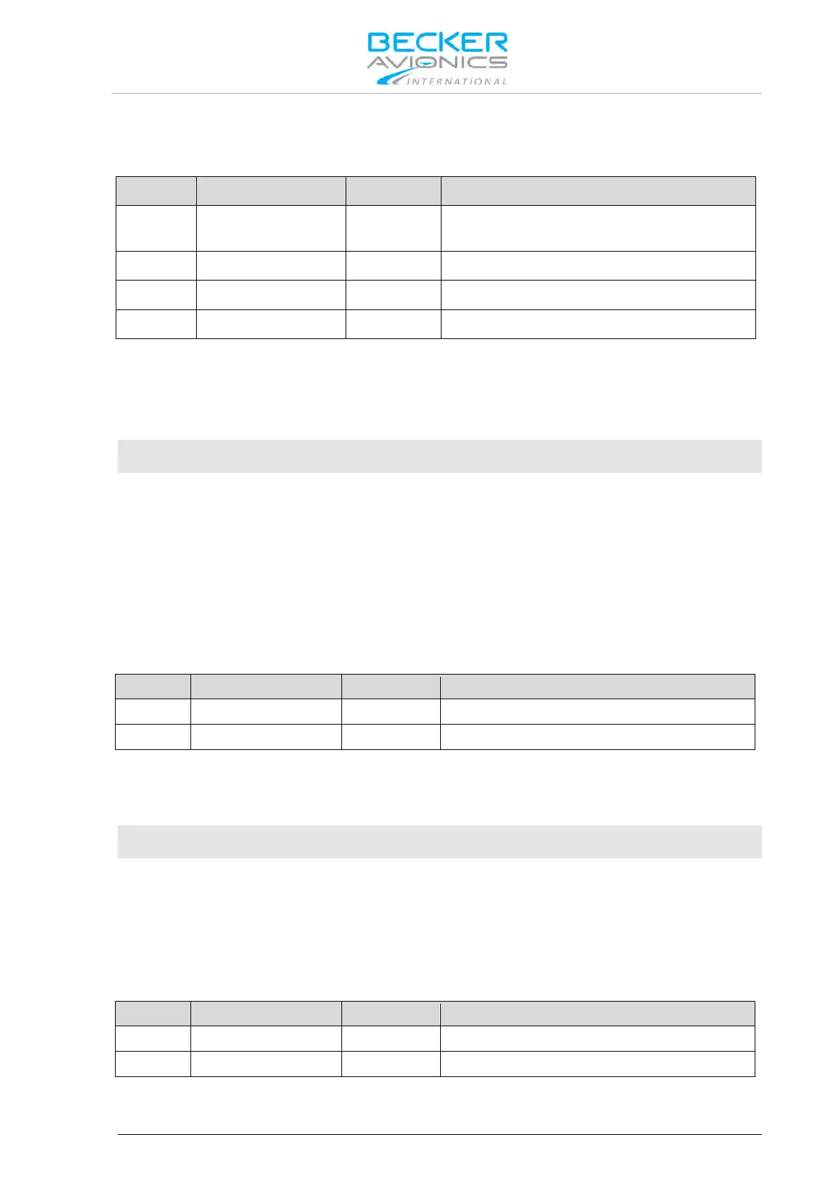
Microphone Connection – Standard Microphones
Standard microphone(s) low (ground/return)
used for STD1, STD2 and STD3
Standard microphone 2 high (hot)
Standard microphone 1 high (hot)
Standard microphone 3 high (hot)
The transceiver has three unbalanced inputs STD1, STD2 and STD3. Each input has an input
impedance of 110 Ω and a nominal sensitivity of 110 mV.
This sensitivity level is adjustable in the configuration setup from 9...1500 mV independently for each
of the microphones. The power supply delivered from pins P1-9, P1-18 and P1-19 for supply of the
connected microphone(s) is > 8 V DC (8.3 V nominal) open circuit with an output impedance of 120 Ω.
Note:
• Sensitivity range 25...1000 mV was qualified under environmental conditions.
• The AR/RT620X transceiver family provides power supply to support two microphones in
parallel on each of the three standard microphone inputs. Combining only microphones of
the same type / impedance is always highly recommended.
• In installations where high interferences were detected, we recommend the use of
sensitivity levels between 27...1500 mV.
• We also recommend mounting the jacks generally isolated from aircraft frame in order to
avoid ground loops.
Microphone Connection - Dynamic Microphone
Balanced input for dynamic microphone(s)
Balanced input for dynamic microphone(s)
Interfacing with dynamic microphones, the transceiver provides balanced inputs with an impedance of
140 Ω and a nominal sensitivity of 1.6 mV. This sensitivity level is adjustable in the configuration setup
from 1...20 mV. Two dynamic microphones in parallel may be connected (identical technical
characteristics of the microphones are preferable).
Note:
• The sensitivity range of 1...20 mV was qualified under environmental conditions. In
installations where high interferences are detected we recommend the use of sensitivity
levels between 2...20 mV.
• We also recommend mounting the jacks generally isolated from aircraft frame in order to
avoid ground loops.
Speaker Connection
The speaker output provides nominal 4 W into 4 Ω.