Installation
Electrical Interface
44 Transceiver Family 620X DV14307.03 Issue 04 March 2016
2.5. Electrical Interface
2.5.1. Connector and Pin Assignment (AR620X and RT6201)
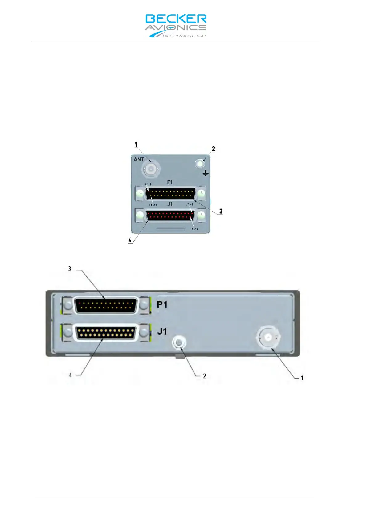
Antenna Connector (Position 1)
The antenna connector (Figure 2-14, position 1) is a BNC type. The antenna port designed for
operating with a nominal impedance of 50 Ω.
Grounding Bolt (Position 2)
The transceiver has a M4 threaded grounding bolt (Figure 2-14,position 2) allowing a low impedance
grounding of the unit, which is essential to avoid damage or malfunction in the case of indirect
lightning, EMI and HIRF conditions.
Figure 2-14: Rear plate AR6201 and RT6201, connectors P1 (male) and J1 (female)
Figure 2-15: Rear plate AR6203, connectors P1 (male) and J1 (female)