Installation
Electrical Interface
DV14307.03 Issue 04 March 2016 Transceiver Family 620X 45
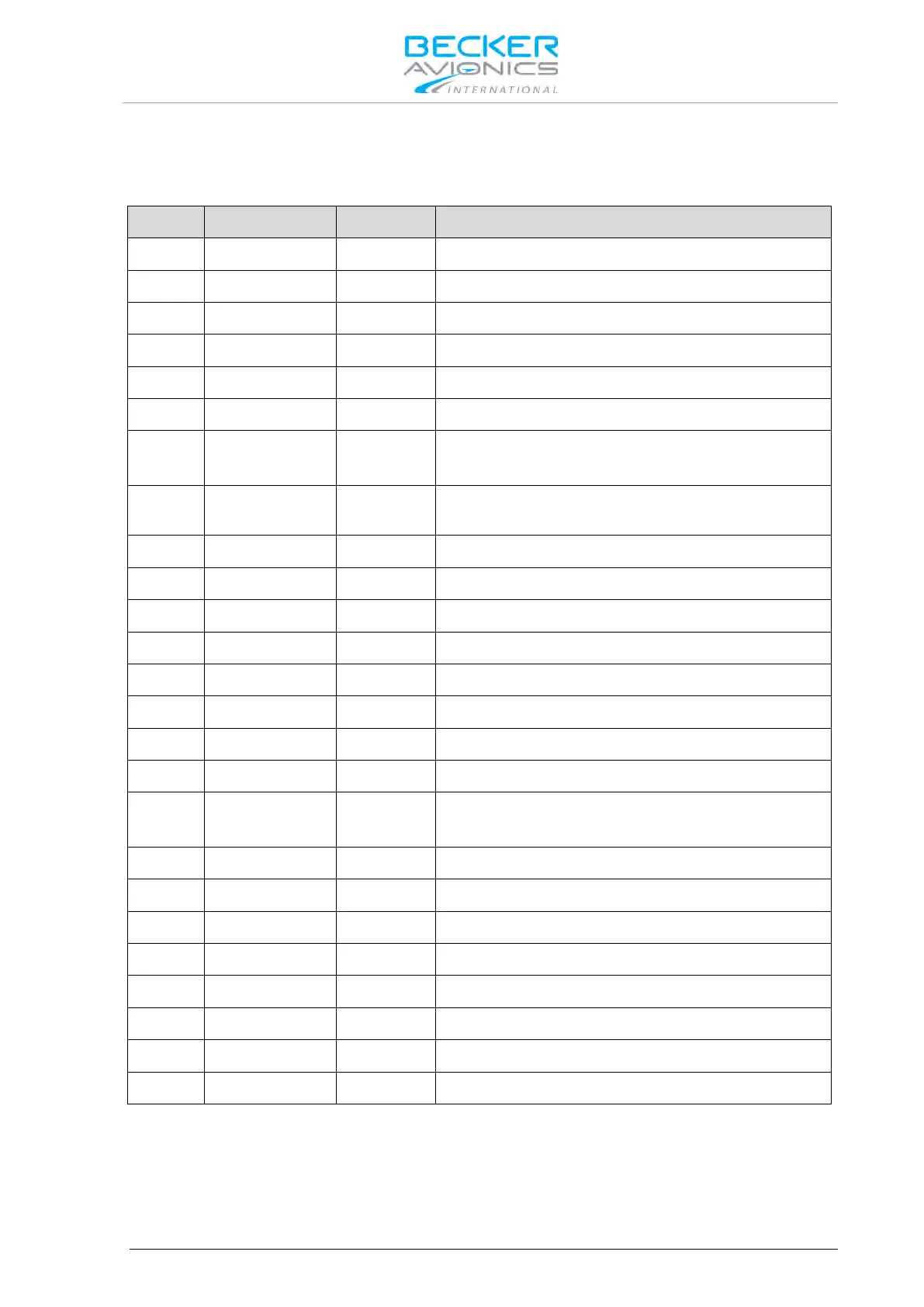
P1 Connector (System Interfaces)
The P1 connector (Figure 2-14 and Figure 2-15, Position 3) is a DSUB male connector with 25 pins
and slide-in fastener.
Speaker output signal (hot)
Balanced output for headphone(s)1
Balanced output for headphone(s)1
Auxiliary audio input (hot)
Balanced input for dynamic microphone(s)
Balanced input for dynamic microphone(s)
ACTIVE state - closed contact to GND
Standard microphone(s) low (ground/return) used for
STD1, STD2 and STD3
Standard microphone 2 High (hot)
Power supply Hot (positive)
Power supply Hot (positive)
Power supply ground (return)
Linear audio output, unbalanced
ACTIVE state - closed contact to GND
Standard Microphone 1 High (hot)
Standard Microphone 3 High (hot)
Balanced Output for headphone(s)2
Auxiliary audio input low (return)
Balanced output for headphone(s)2
Power supply ground (return)