Installation
Wiring Diagrams and Settings
DV14307.03 Issue 04 March 2016 Transceiver Family 620X 83
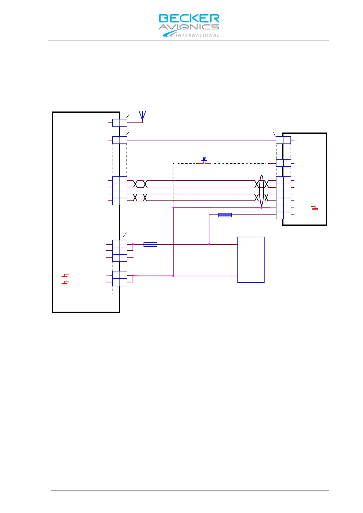
2.10.7. Installation with RT6201 and RCU6201
RT6201 with primary controller RCU6201 can be used in all presented installation wirings. RT6201
with RCU6201 replace a AR620X. The connection between RT6201 and RCU6201 is shown in the
wiring diagram below.
2.10.7.1. Wiring Diagram with RT6201 and RCU6201
ANTENNA
7.5 A
3 A
AWG20
AWG20
Frequency Exchange
(Remote Flip-Flop)
optional
J3
J1
P1
P1
ANTENNA
/ON
RX2+
RX2-
TX2+
TX2-
/EXT_ON
/EXCH_CH
TX0_422+
TX0_422-
RX0_422+
RX0_422-
GND
SUPP_IN
A
A
24
24
12 12
11 11
13 13
25 25 13 13
15 15
1 1
2 2
4 4
5 5
9 9
11 11
25 25
10 10
3 3
2 2
9
9
RT6201-(X1X) / RT6201-(X2X)
RCU6201-(X1X)
P_SUPP
P_SUPP
/PWR_EVAL
P_SUPP_GND
P_SUPP_GND
+
-
SUPPLY
14 V / 28 V
Figure 2-26 Wiring for RT6201 with RCU6201 as Primary Controller