Installation
Wiring Diagrams and Settings
76 Transceiver Family 620X DV14307.03 Issue 04 March 2016
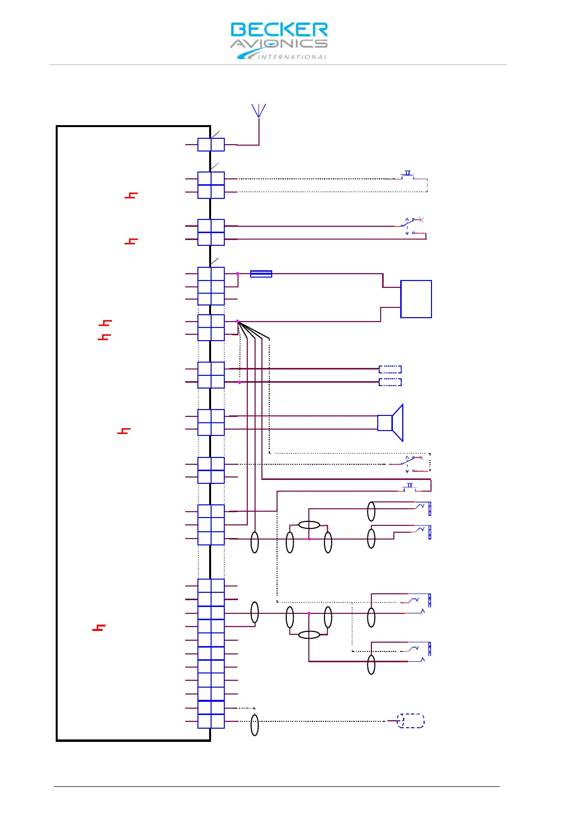
2.10.3.2. Wiring Diagram General Aviation GA Using Standard Microphones
J3
J1
P1
A
A
12 12
21 21
24
23
23
24
12 12
11 11
24 24
13 13
25 25
23 23
10 10
14 14
7 7
16 16
17 17
3
3
2 2
5 5
6
6
18 18
88
9 9
21 21
20 20
19 19
4
4
15 15
22 22
1 1
ANTENNA
/EXT_SO
ILL_HI
SPK_HI
SPK_LO
/IC
AGC_OUT
/PTT1
HDPH1_B
HDPH1_A
HDPH2_B
HDPH2_A
MIKE_DYN_LO
MIKE_DYN_HI
MIKE_STD1_HI
MIKE_STD2_HI
MIKE_STD3_HI
LINE_OUT
AF_AUX_IN_LO
AF_AUX_IN_HI
MIKE_STD1_LO
ILL_LO
/MIKE_SW
D_GND
D_GND
P_SUPP
P_SUPP_GND
P_SUPP_GND
P_SUPP
/PWR_EVAL
AR6201-(X1X) / AR6203-(X1X)
AR6201-(X2X) / AR6203-(X2X)
ANTENNA
Frequency Exchange
(Remote Flip-Flop)
optional
SPEAKER Off
SPEAKER On
AWG20
7.5 A
+
-
AWG20
SUPPLY
14 V / 28 V
Dimming Control
14 V / 28 V
GND
SPEAKER
4 Ohm
AWG20
Manual Intercom (optional)
Intercom Off
Intercom On
PTT
Earphone Pilot
PJ055
Earphone Copilot
PJ055
PJ068
Standard Mike
Pilot
PJ068
Standard Mike
Copilot
Auxiliary Audio Input
Note: mount the jacks
(earphone&mike) isolated from aircraft frame
optional
Figure 2-22: Wiring for Usage of Standard Hand Mikes, Earphones and Speaker