Installation
Wiring Diagrams and Settings
86 Transceiver Family 620X DV14307.03 Issue 04 March 2016
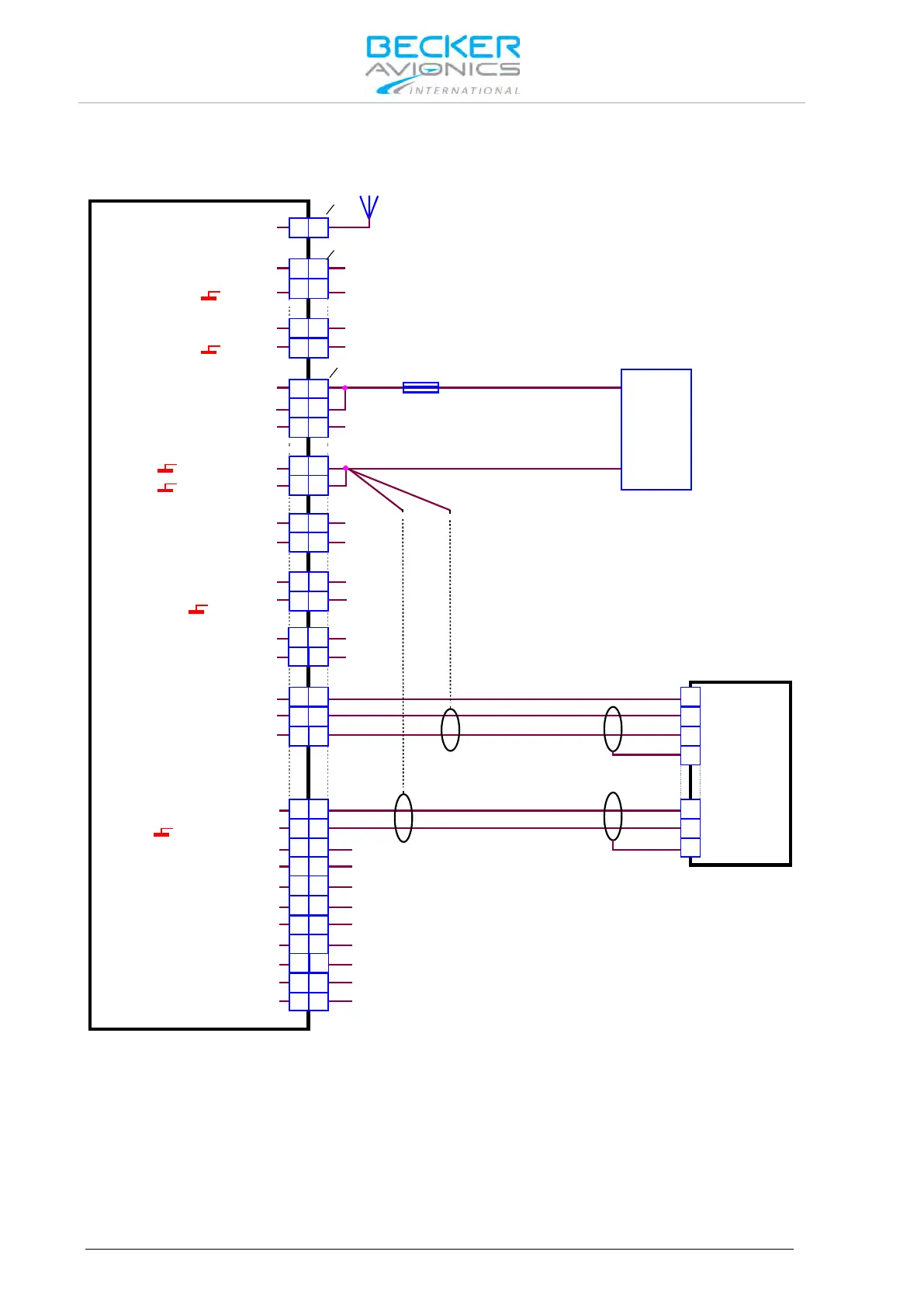
2.10.8.3. Wiring Diagram Aircraft with Intercom System Balanced
AR6201-(X1X) / AR6203-(X1X)
AR6201-(X2X) / AR6203-(X2X)
ANTENNA
J3
J1
P1
ANTENNA
/EXT_SO
D_GND
/MIKE_SW
D_GND
HDPH1_B
HDPH1_A
P_SUPP
P_SUPP_GND
P_SUPP_GND
ILL_HI
ILL_LO
SPK_HI
SPK_LO
/IC
AGC_OUT
/PTT1
P_SUPP
/PWR_EVAL
A
A
23 23
25 25
10 10
1 1
14 14
7 7
16 16
12 12
21 21
23 23
17 17
12 12
11 11
24 24
3 3
2 2
5 5
6 6
18 18
88
9 9
2222
2020
19 19
1515
21
MIKE_DYN_LO
MIKE_DYN_HI
MIKE_STD1_HI
MIKE_STD_LO
MIKE_STD2_HI
MIKE_STD3_HI
LINE_OUT
AF_AUX_IN_LO
AF_AUX_IN_IN
HDPH2_B
HDPH2_A
21
44
1313
24
24
+
-
SUPPLY
14 V / 28 V
Intercom System
AWG20
7.5 A
AWG20
Note:
Optional grounging to PIN13,
if grounding of shields is needed
on both cable ends.
PIN N
PIN N
PIN N
PIN N
PIN N
PIN N
PIN N
Figure 2-28: Wiring for Aircraft with Intercom System (balanced)