Installation
Mechanical Installation
DV14307.03 Issue 04 March 2016 Transceiver Family 620X 41
2.4.3. RT6201 Installation
Install the RT6201 at a suitable place in the aircraft for example directly on avionic bay or by using
mounting kit MK6201-(010).
To meet the conditions for certification use the mounting method with
mounting kit.
The mounting location for RT6201 shall be at least 30 cm away from the aircraft magnetic compass, to
avoid any interference to the magnetic compass by the transceiver. Leave a clearance of minimum
5 mm between the RT6201 and other avionics to allow air circulation. Forced cooling is usually not
required.
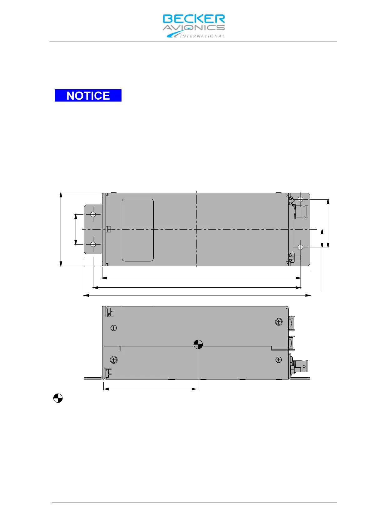
RT6201: Installation using RT6201 Mounting Holes
The required dimensions for installation using the mounting holes on the RT6201 are given in
Figure 2-11 (dedicated holes are marked with "X" letter).
Dimensions mm (inch)
CENTER OF GRAVITY
85 (3.346 in)
188±1 (7.4 in ±0.4)
172.5±1 (6.79 in ±0.4)
164.9±0.5 (6.49 in ±0.196)
15
(0.59 in)
40
(1.57 in)
61 (2.4 in)
25 (0.98 in)
Figure 2-8: RT6201 top view, side view