Installation
Mechanical Installation
36 Transceiver Family 620X DV14307.03 Issue 04 March 2016
2.4. Mechanical Installation
The device must not be opened.
When installing the device, make sure the heat dissipators of the
device receive sufficient air. Keep an efficient distance of the devices
with integrated ventilator fans in order to ensure free circulation of the
cooling air.
Make sure that the mounting plate is not exposed to external
temperature influences.
The mounting place shall be at least 30 cm from the magnetic aircraft
compass, to avoid any interference to the magnetic compass (there
are no restrictions for RCU6201mounting).
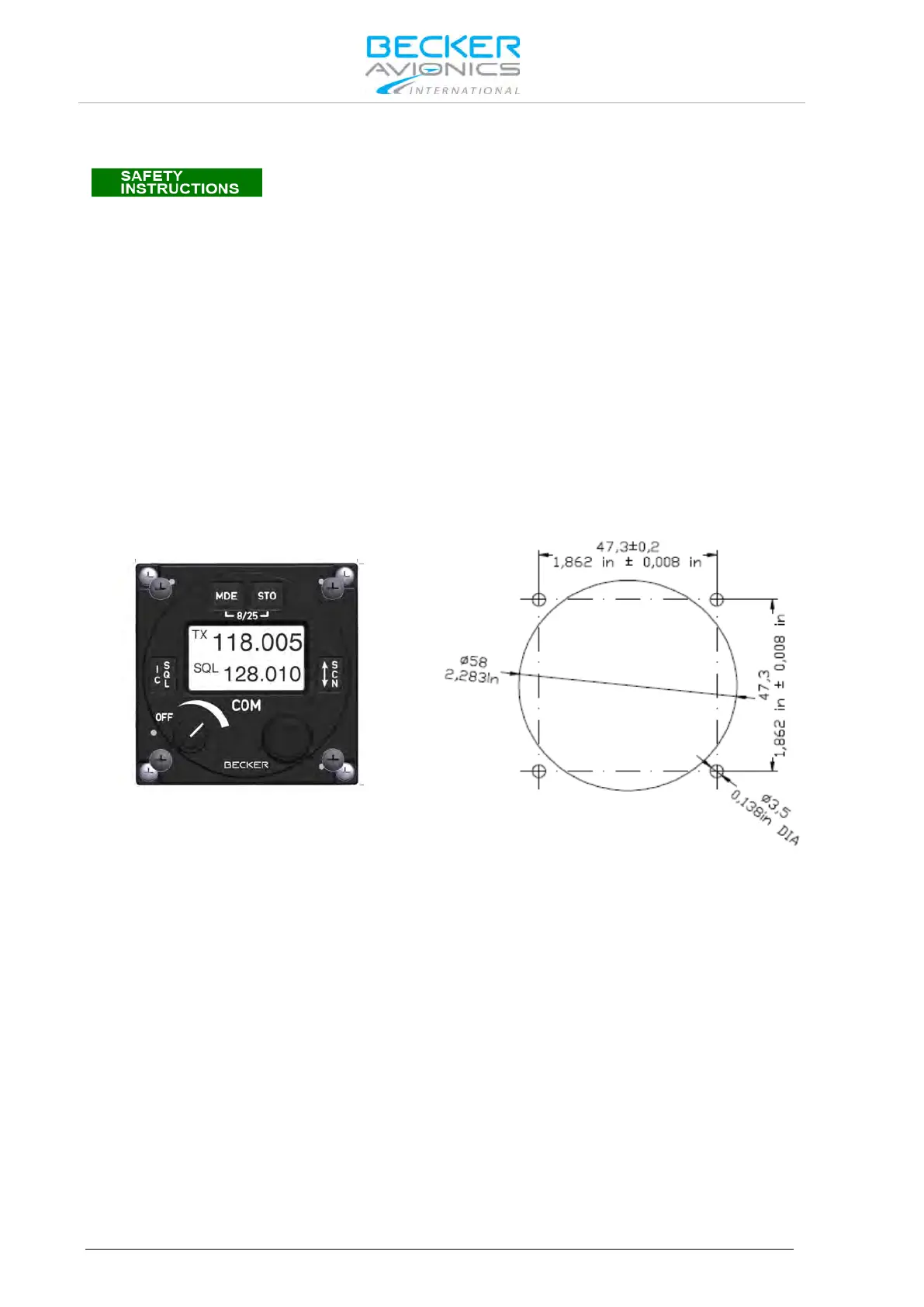
2.4.1. AR6201 and RCU6201 Installation (Back Panel Mounting)
Leave a clearance of minimum 5 mm between the AR6201 respectively RCU6201 and other avionics
to allow air circulation. Forced cooling is usually not required. For installation via rear side of the panel,
four screws already attach to the front of the unit. The circular cut out and the mounting holes have to
be prepared in accordance with Figure 2-3. For unit dimensions refer to Figure 2-5, Figure 2-4 and
Figure 2-2.
61x61 mm (2.4x2.4 in)
Figure 2-2: AR6201 and RCU6201 front view
Figure 2-3: Drilling template (back-panel mounting)