Installation
Electrical Interface
46 Transceiver Family 620X DV14307.03 Issue 04 March 2016
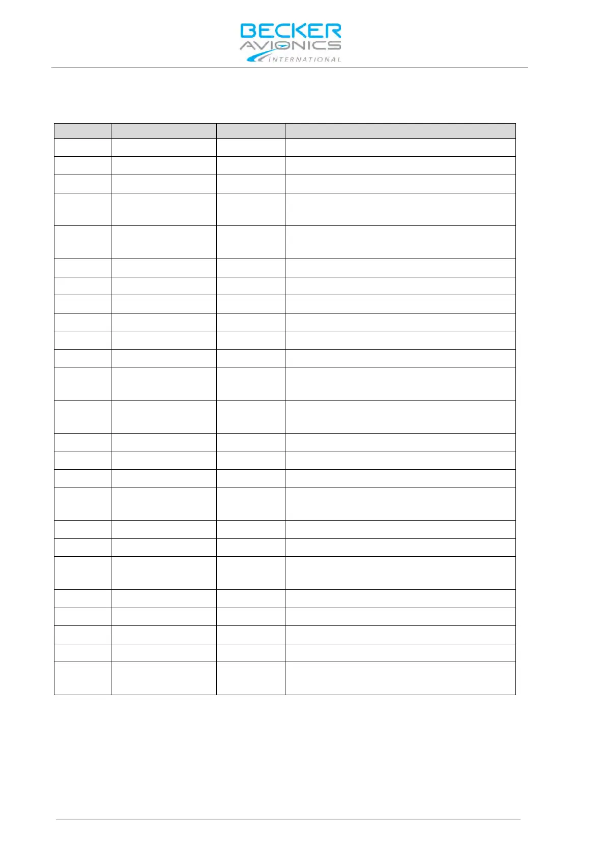
J1 Connector (Serial Interfaces and Discrete I/O’s)
The J1 connector is a D_SUB female connector with 25 sockets and slide-in fastener.
Auxiliary control interface
Auxiliary Control Interface
ACTIVE state - closed contact to GND
Press-To-Talk key input 2
ACTIVE state - closed contact to GND
Secondary control & service interface SHIELD
Secondary control & service interface
Secondary control & service interface
Auxiliary control interface
Auxiliary control interface
Auxiliary control interface SHIELD
Falling edge will activate frequency exchange
ACTIVE state - closed contact to GND
Secondary control & service interface
Secondary control & service interface
"Squelch Force-OFF" input
ACTIVE state - closed contact to GND
ACTIVE state - closed contact to GND
Configuration selector CFG1 and CFG2
ACTIVE state - closed contact to GND