BENNING IT 130 Device description
- 14 -
3 Device description
3.1 Front panel
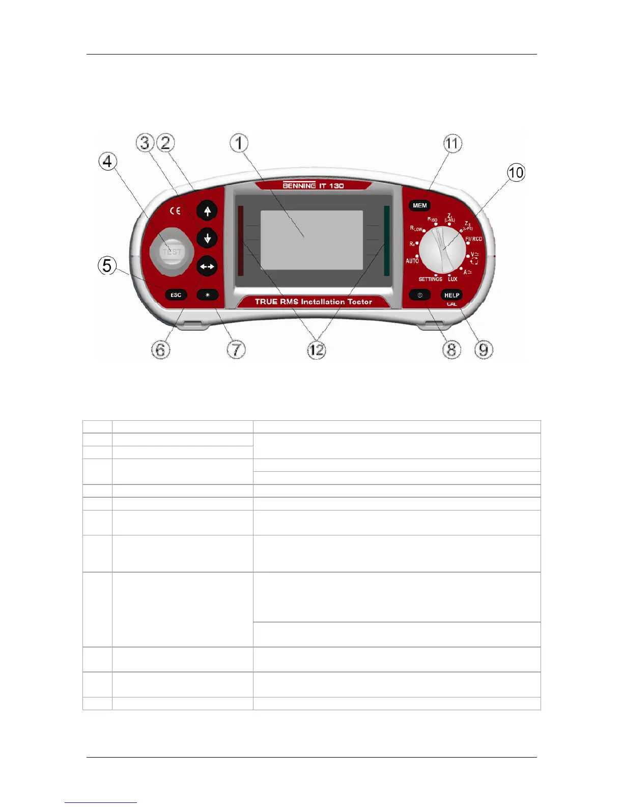
Figure 3.1: Front panel
Caption:
1
LCD
Matrix display with 128 x 64 pixels and background lighting
2
UP
3
DOWN
Modifies selected parameters
Start of measurement
4
TEST
PE contact electrode for protective conductor connection
5
ESC
Back / cancel
6
TAB
Selects parameters in the measuring function selected
7
Backlight,
Contrast
Modifies background lighting and contrast
8
ON / OFF
Switches the tester on or off;
automatic switch-off ("APO") after 15 minutes without
pressing a key
Help function with connection diagrams
(press approx. 2 seconds for R LOW and ∆U)
For calibrating the test cables in the R LOW and
CONTINUITY function
9
HELP / CAL
Starts the Z
REF
measurement in the sub-function ∆U
voltage drop
10
Function selector switch
Rotary switch for selecting the measuring functions,
"AUTO" switch position and "SETTINGS" mode
11
MEM
Storage / recall of measuring results;
stores the settings of the current clamp adapter
12
Green / red LED
PASS / FAIL indication of the measuring results