BENNING IT 130 Measurements
- 48 -
5.6 Line impedance and prospective short-circuit current /
voltage drop
The line impedance is a complex AC resistance within a current loop (short-circuit L-N or L-L)
consisting of current source, external and neutral conductor (single-phase system) or between
two external conductors (three-phase system).
The line impedance measurement complies with the requirements specified in the EN 61557-3
standard.
The "voltage drop" sub-function is intended to check whether a voltage in an electrical
installation remains above an admissible value, if the maximum nominal current of the upstream
fuse is flowing in the circuit. The limiting values are described in the EN 60364-5-52 standard.
Sub-functions:
Zline – line impedance measurement in compliance with EN 61557-3 and
∆U – voltage drop measurement
Key function as described in chapter
4.2 Function selector switch
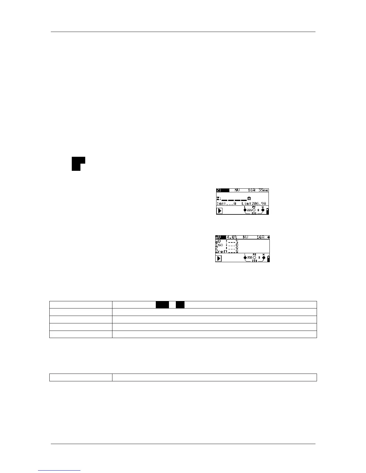
Figure 5.26:
Line impedance
Figure 5.27:
Voltage drop
Testing parameters
Test
Sub-functions [Zline], [∆U]
Fuse type
Selects the fuse type [---, gL/gG, B, C, K, D]
Nominal current
Nominal current of the fuse
Tripping time
Maximum tripping time of the fuse
Lim (limiting value)
Lower limit of the prospective short-circuit current
See Appendix A "Fuse table".
Additional testing parameter for voltage drop measurement:
∆U
MAX
Maximum voltage drop [3.0 % ÷ 9.0 %]