BENNING IT 130 Appendix C – Commanders
- 86 -
C.3 Description of the "Commanders"
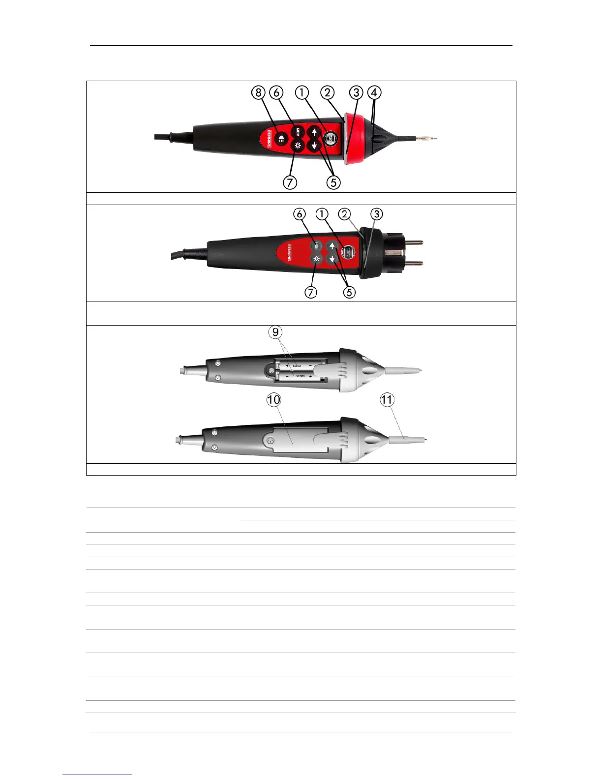
Figure C.1: Front of "Commander" test probe (switchable by means of "TEST" key)
Figure C.2: Front of the optional "Commander" test plug for shock-proof socket
(switchable by means of "TEST" key) (044149)
Figure C.3: Rear of the "Commander" test probe
Caption:
Start of measurement 1
TEST
PE contact electrode for protective conductor connection
2
LED
Left status RGB LED
3
LED
Right status RGB LED
4
LEDs
LEDs of the measuring point illumination
5
Function selector keys
Selection of the measuring function (only in the "AUTO"
switch position)
6
MEM
Storage / recall of measuring results
7
LCD illumination
Switches on / off the LCD illumination of the installation
tester
8
Measuring point
illumination
Switches on / off the measuring point illumination
9
Batteries / storage
batteries
Size AAA, alkaline batteries or NiMH storage batteries
10
Battery compartment
cover
Battery compartment cover
11
Protective cap
Detachable protective cap, CAT IV 300 V