BENNING IT 130 Measurements
- 34 -
5.2 Insulating resistance
The measurement of the insulating resistance is performed in order to prove the proper
condition of the insulation and in order to exclude electrical danger.
Typical applications are the following cases:
Insulating resistance between the active conductors (L/N) of an installation and the
protective conductor / earth (PE) => protection against electric shock,
Insulating resistance between the active conductors (L/N) of an installation => protection
against short-circuit (over-current) and guarantee of the functional safety,
Insulating resistance of non-conductive rooms (walls and floors),
Insulating resistance of earthing cables and
Resistance of semiconductive (antistatic) floors.
Key function as described in chapter
4.2 Function selector switch
Figure 5.5:
Insulating resistance
Testing parameters
Uiso Nominal testing voltage [50 V, 100 V, 250 V, 500 V, 1000 V]
Limiting value
Minimum insulating resistance [without limits (---), 0.01 MΩ ÷ 200 MΩ]
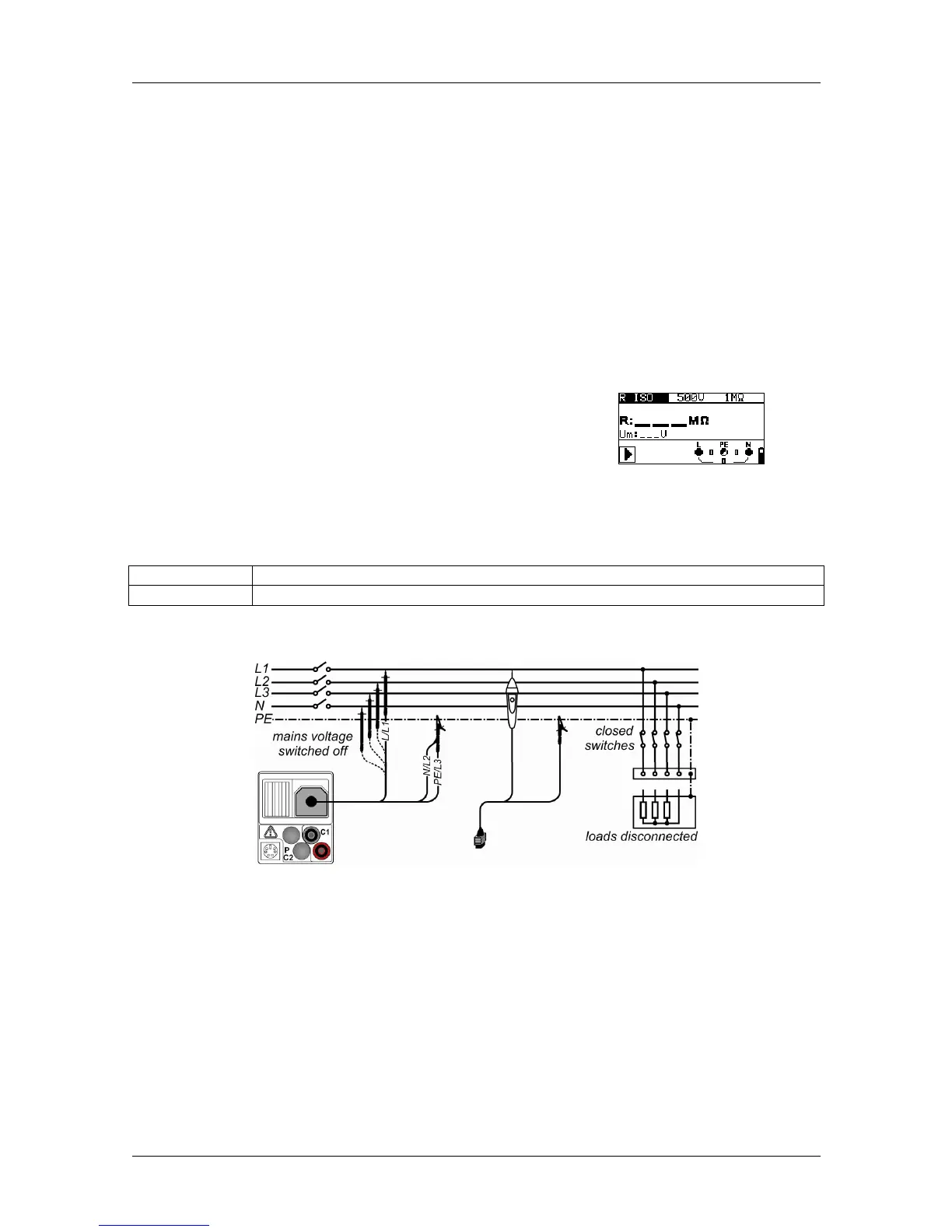
Connection plan
Figure 5.6: Connection of the three-wire test cable and the "Commander" test probe