BENNING IT 130 Measurements
- 33 -
How to perform voltage measurements
Select the
V≅
≅≅
≅
function by means of the function selector switch. The display shows
VOLTAGE TRMS.
Connect the test cables to the test object (see figure 5.2 and figure 5.3).
Save the measuring result by pressing the "MEM" key.
The measurement is performed immediately after the VOLTAGE TRMS function has been
selected.
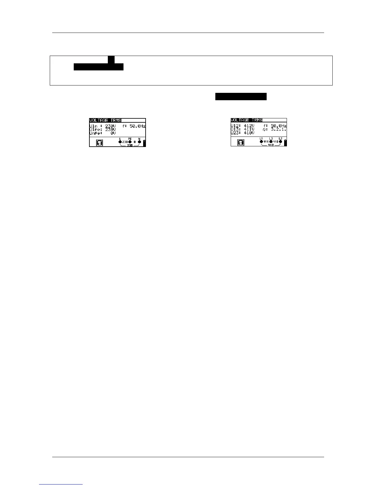
Figure 5.4: Examples for voltage measurements in single-phase and three-phase systems
Results displayed for single-phase systems:
Uln ........... voltage between phases and neutral conductor
Ulpe ......... voltage between phase and protective conductor
Unpe ........ voltage between neutral and protective conductors
f................ frequency
Results displayed for three-phase systems:
U12........... voltage between testing terminals L1 and L2
U13........... voltage between testing terminals L1 and L3
U23........... voltage between testing terminals L2 and L3
1.2.3 ......... correct connection – clockwise phase sequence
3.2.1 ......... wrong connection – counter-clockwise phase sequence
f................ frequency
Results displayed for IT systems:
U12........... voltage between testing terminals L1 and L2
U1pe ........ voltage between testing terminals L1 and PE
U2pe ........ voltage between testing terminals L2 and PE
f................ frequency