BENNING IT 130 Measurements
- 43 -
Norm EN 61008/EN 61009, (SETTINGS mode → RCD TESTING):
Increasing fault current
RCD type
Initial value Final value
Curve
shape
AC
0,2×I
∆N
1,1×I
∆N
sinusoidal
A, F (I
∆
∆∆
∆N
≥
≥≥
≥ 30 mA)
0,2×I
∆N
1,5×I
∆N
A, F (I
∆
∆∆
∆N
= 10 mA)
0,2×I
∆N
2,2×I
∆N
pulsating
B, B+
0,2×I
∆N
2,2×I
∆N
DC
The maximum testing current is I
∆
(tripping current) or corresponds to the final value, if the RCD
does not trip.
How to perform tripping current measurements
Select the FI/RCD function by means of the function selector switch.
Set the sub-function to RCD I.
Set the testing parameters.
Connect the test cables to the test object (see figure 5.17).
Press the "TEST" key to start the measurement.
Save the measuring result by pressing the "MEM" key (optional).
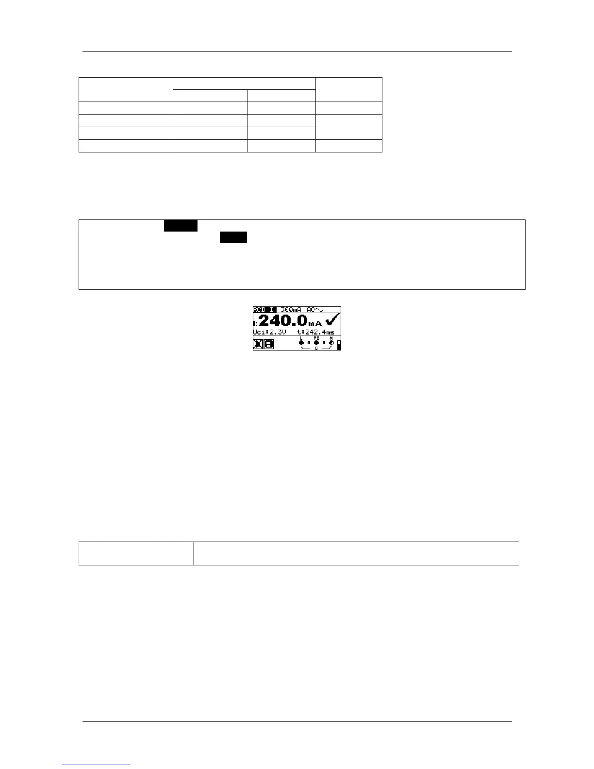
Figure 5.20: Example of a tripping current measurement
Results displayed:
I ...........tripping current
Uci .......contact voltage at tripping current I or final value, if RCD does not trip
t............tripping time
5.4.4 Automatic test
The automatic RCD test is intended to perform a complete RCD test (tripping time at different
fault currents, tripping current and contact voltage) in a sequence of automatic tests controlled
by the installation tester.
Additional key
HELP / DISPLAY As soon as measurement is finished, the "HELP" key toggles between
the upper and lower part of the result field.