BENNING IT 130 Measurements
- 36 -
5.3 Low-impedance resistance / continuity test
The measurement of the low-impedance resistance / continuity test is intended for testing the
protective conductor, earthing conductor and equipotential bonding conductor connections of an
electrical installation.
Two sub-functions are available:
R LOWΩ – resistance measurement in compliance with EN 61557-4 with a testing
current of 200 mA and polarity reversal
CONTINUITY – continuous continuity test with a reduced testing current of 7 mA.
Key function as described in chapter
4.2 Function selector switch
Figure 5.8: Low-impedance
resistance RLOW Ω with a testing
current of 200 mA
Testing parameters
Test Sub-function [R LOWΩ, CONTINUITY]
Limiting value Maximum resistance [without limits (---), 0.1 Ω ÷ 20.0 Ω]
Additional testing parameter for continuity test sub-function:
Buzzer ON (sounds if the resistance is lower than the limiting value set) or OFF
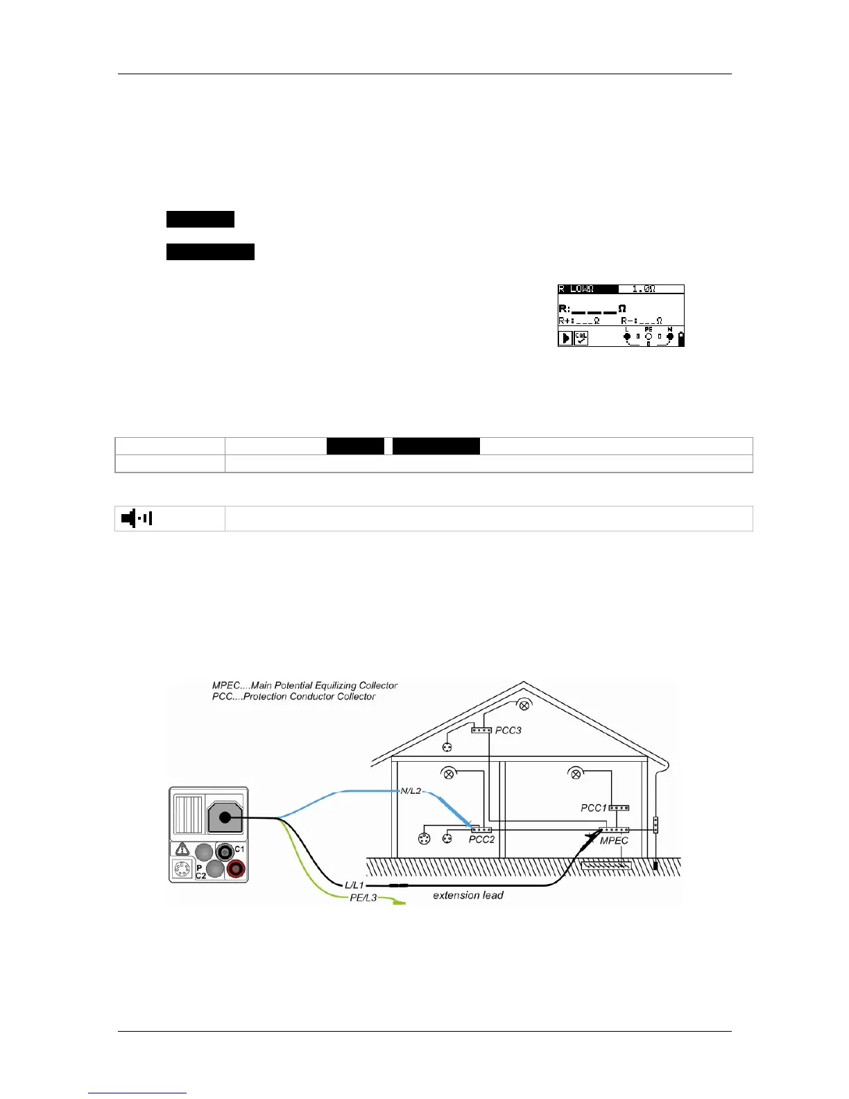
5.3.1 Low-impedance resistance with a testing current of 200 mA
The resistance measurement is performed with automatic polarity reversal of the testing
voltage.
Connection plan
Figure 5.9: Connection of the three-wire test cable and the
optional 40 m measuring line BENNING TA 5 (044039)