BENNING IT 130 Measurements
- 37 -
How to perform low-impedance measurements R LOWΩ
Select the R
LOW
function by means of the function selector switch.
Set the sub-function to R LOWΩ.
Set the limiting value (optional).
Connect the test cables to the installation tester and compensate the test cable
resistance, if necessary (see section 5.3.3 Compensation (null balance) of the test cable
resistance).
Make sure that the test object is free of voltage and discharge available capacities.
Connect the test cables to the test object (see figure 5.9).
Press the "TEST" key to start the measurement.
Save the measuring result by pressing the "MEM" key (optional).
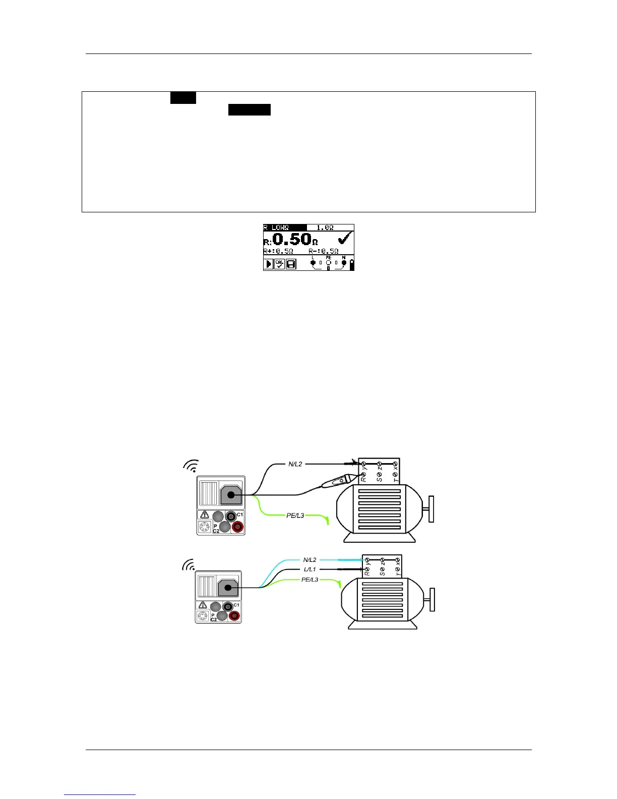
Figure 5.10: Example of a low-impedance measurement RLOW
Ω
Results displayed:
R .............. R LOWΩ – low-impedance resistance
R+ ............ partial result at positive polarity
R- ............. partial result at negative testing polarity
5.3.2 Continuity test with a testing current of 7 mA
This test function can be compared to the continuity test function of a digital multimeter or of a
continuity tester with low testing current. The continuous test is done without polarity reversal
and can be used for testing inductive components.
Connection plan
Figure 5.11: Using the "Commander" test probe and the three-wire test cable