BENNING IT 130 Measurements
- 53 -
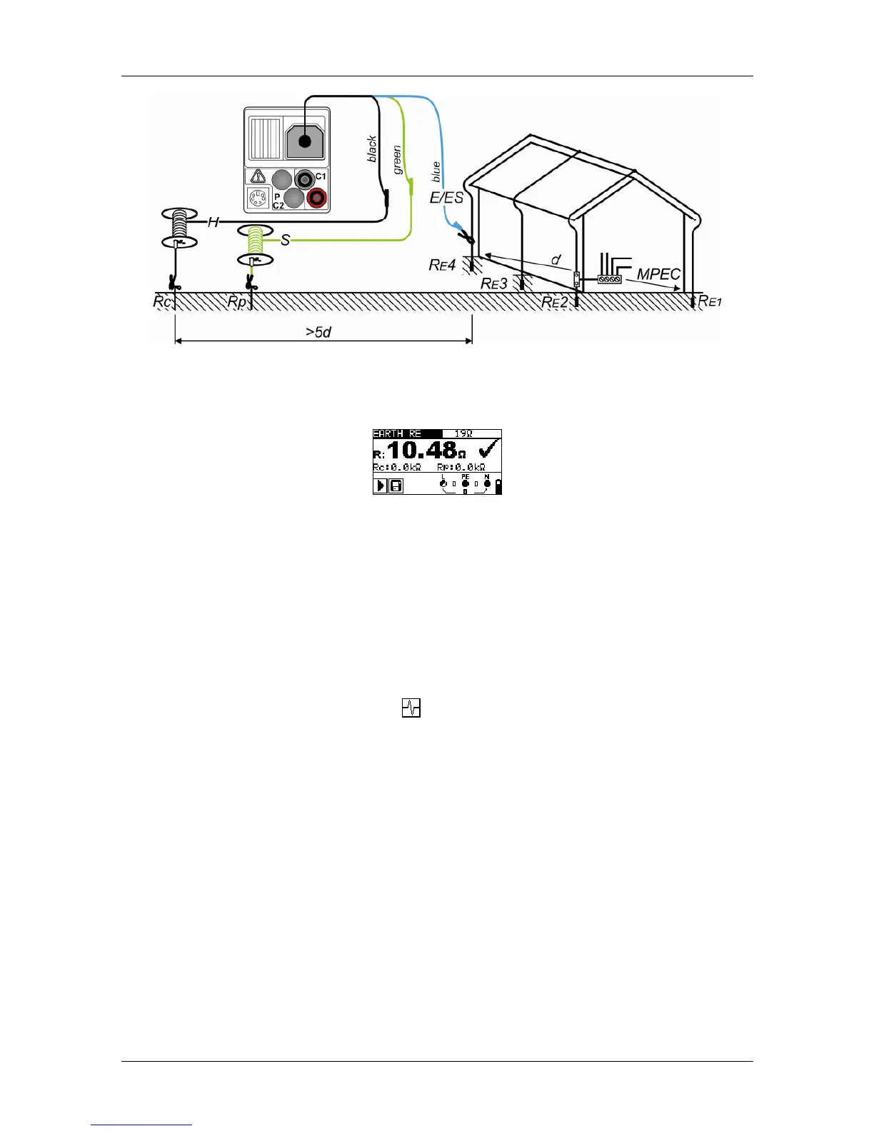
Figure 5.34: Connection of the optional earthing kit (044113)
– Measurement at the lightning arrester
Figure 5.35: Example of an earthing resistance measurement
Results displayed:
R .............. earthing resistance
Rp ............ resistance of the S probe, probe resistance (potential)
Rc ............ resistance of the H probe, auxiliary earth electrode resistance (current)
Notes:
An excessive resistance of the S and H probes might influence the measuring results. In
this case, the warnings “Rp” and “Rc” will be displayed. The results will not be evaluated
with "PASS" / "FAIL".
High parasitic currents and interference voltages might influence the measuring results.
In this case, the tester displays the warning.
The probes must be positioned with sufficient distance from the test object. The distance
between the earth connection (E/ES) and the probe (H) should be at least five times
larger than the depth or length of the earth connection (see figures 5.33 and 5.34).