Section 5 Getting Started
39
5.2 Getting Started
The system has to be taken into operation as follows:
Turn instrument on
by connecting it to mains. The manufacturer
name, version number and instrument type are displayed (Figure
26).
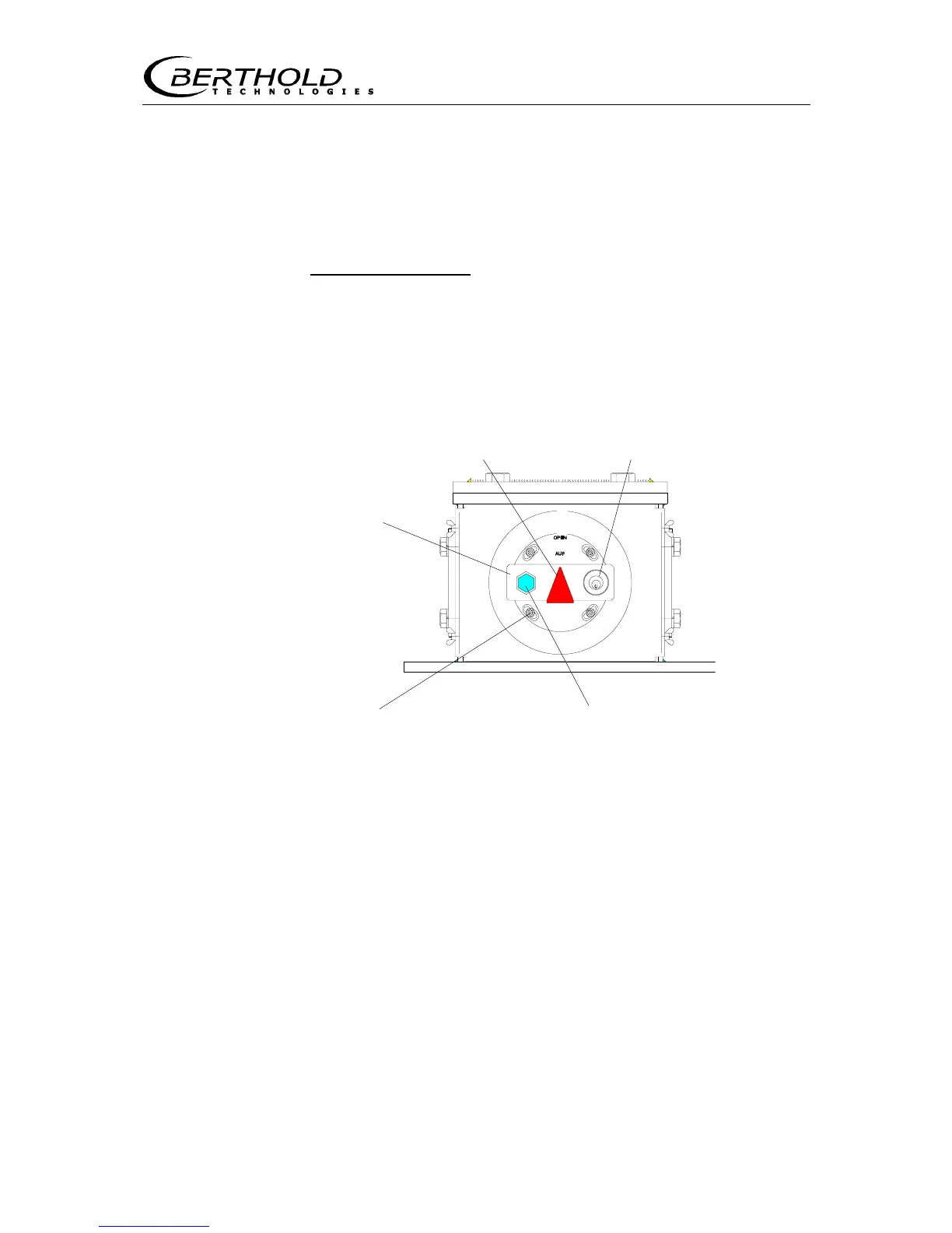
5.2.1 Opening the Radiation Exit Channel
(e)
OPEN position (c) Lock
(d) Threaded (b) Hexagon head cap screw for
bore hole arresting the shielding
Figure 24: Shielding (side view) in foot of measuring frame
Display: radiation exit channel OPEN
Opening the radiation exit channel)
1. Unscrew hexagon head cap screw (b) at lever (a).
2. Insert key in lock (c).
3. Push in lock and turn key to open the lock. Now you can move
the radiation exit channel by turning the lever (a).
4. Turn lever until the arrow points straight up and the bore hole
on the metal plate sits over the respective threaded bore hole.
5. Turn in hexagon head cap screw and tighten it firmly (!). The
source must sit absolutely tight, so that possible vibrations of
the conveyor system cannot move the source in the shielding.
6. Turn key in lock and pull it out.
Lever (a) fo