6.1 General Description
48
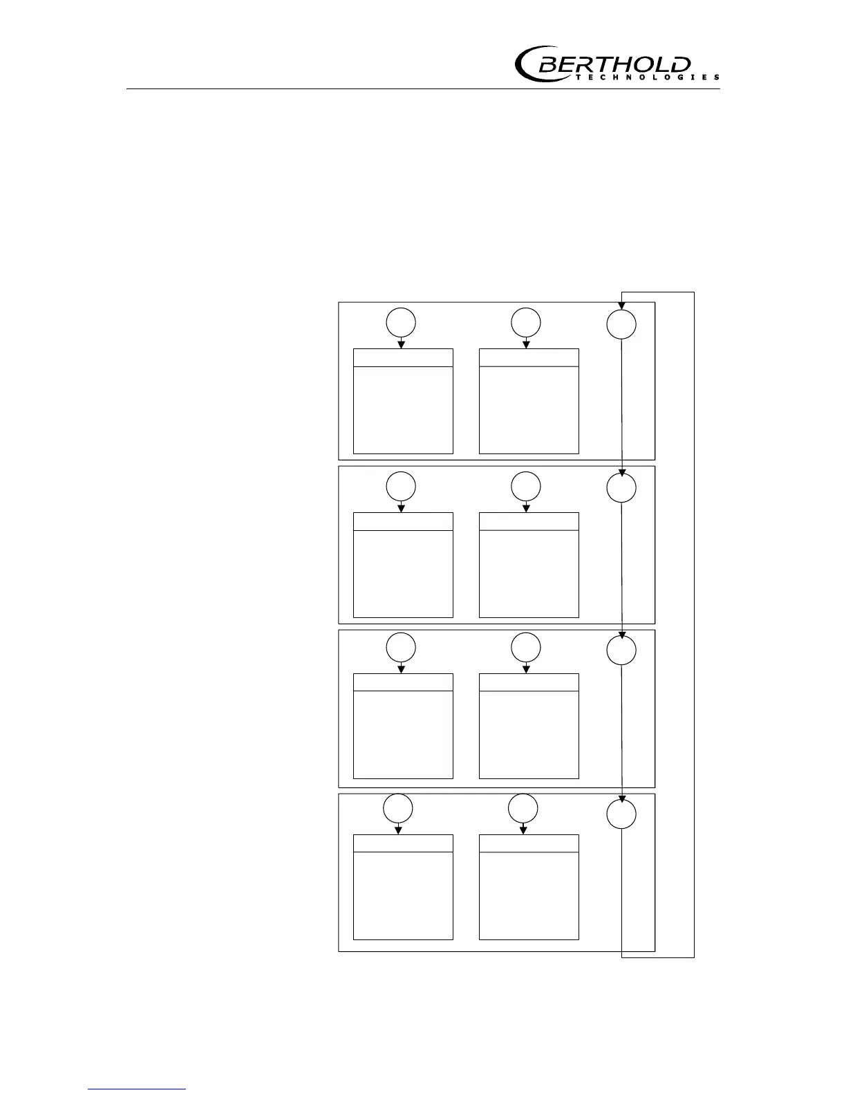
6.1.1 Menu Structure (Flow Chart)
The flow chart below illustrates the menu structure for parameter
input and operation. With <more> you select the various menu
groups and from there you get to the respective menu with <sk1>
or <sk2>. Within the menu you get to the individual windows with
<more> and at the end of the menu you get back to the menu
group with <done>.
General Data
Password
Date & Time
System Version
Detector Soft.
Language
Parameter Print
Factory Setting
Operating Mode
Config. Instrument
Tacho Config
Unit Selection
Error Mode
Loading at Stop
sk1 sk2
Measure. Parameter
Detector / Isotop
Time Constant
Belt Speed
Basis Weight
Width of Belt .
Product Selection
Erase Massintegr.
I/O Config.
Product Selection
Current Output
Dig. In 1 / 2
Dig Out 3
Print Out
sk1 sk2
Calibrate
Tare
Data Input
Calibration Mode
Factor Offset
Live Display
Loading
Totalizer
Detector Temp.
Tare Counts
Speed
Detector HV
Count Rate
sk1 sk2
Service Menu
Test
I/O Test
HV Set-Up
Status Request
Plateau
Current Out Adjust
Pulse Length
Interfaces
RS 232/485
Access Control
Number of Detectors
Slave Address
sk1 sk2
more
more
more
more
Figure 29: Menu structure