4.2 Evaluation Unit LB 442
34
4.2 Evaluation Unit LB 442
Make the connections on the rear panel of the evaluation unit as
shown in the wiring diagram in the appendix to this manual on
page 146.
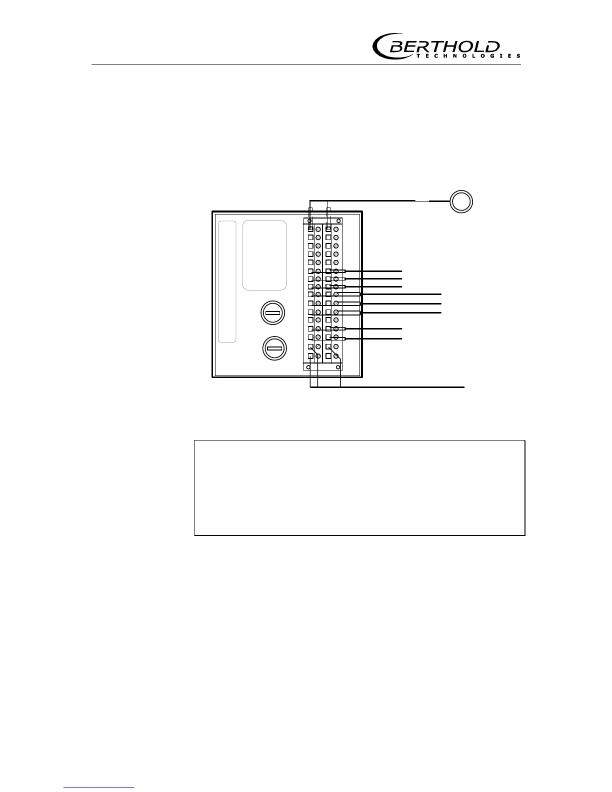
LB 442
Detector
Mains supply
Fuse
ca
2
4
6
8
10
12
14
16
18
20
22
24
26
28
30
32
Relay 1
Relay 2
Relay 3
Dig. In 2
Dig. In 3
Current In (+/-)
Current Out (-/+)
1(+)
2(-)
Voltage
selector
Dig. In 1
Figure 23: Terminal connection evaluation unit (rear panel)
Carefully note the power supply for the instrument and ob-
serve all safety previsions regarding the power supply.
A separate fuse protection and an easy to access shutoff
have to be foreseen, since the evaluation unit does not in-
clude its own mains switch.
Refer to the wiring diagram in the appendix to this manual for the
connections. The terminals are described as follows:
Detector Terminal (2a/2c)
Connection is made via 2-wire technique; the detector protection
type is EEx de IIC T6 or EEx de (ib) IIC T6 or EEx de (ib) IIB T6.
For inherently safe installation, the cable ends on the strip terminal
must be protected by a 10 mm long shrink-down plastic tubing
(see also the connection diagram).