56926BA2, Rev. 02, 04/2019
2
3
4
5
6
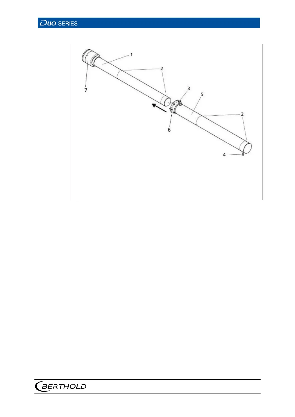
Marker grooves
Water discharge
Water supply
Water cooling system
Connection flange
46 Rod Detector with Water Cooling System
1. Slide the water cooling system (Fig. 46, item 5) with the connecting flange (Fig.
46, item 6) in the direction of the connection chamber
2. Fasten the water cooling system on the detector socket with the enclosed
screws.
Depending on the detector assembly, (horizontally or vertically, connection com-
partment on top or at the bottom) the respective lower cooling water connection
should be used as a feed, so that no air pockets form in the cooling water.