VDL (E3) 09/2019 Page 9/234
List of figures
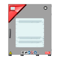
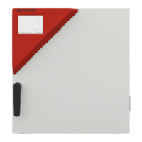
Figure 1: Position of labels on the chamber (examples) ............................................................................. 14
Figure 2: Type plate (example of VDL 115) ................................................................................................ 15
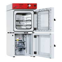
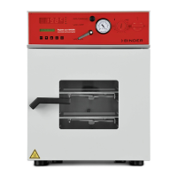
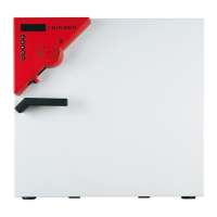
Figure 3: VDL 115 with MB2 controller ....................................................................................................... 45
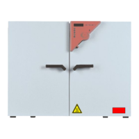
Figure 4: VDL 115 with optional RD4 controller .......................................................................................... 45
Figure 5: Instrument panel with MB2 program controller and USB interface .............................................. 46
Figure 6: Instrument panel with RD4 controller and USB interface ............................................................ 46
Figure 7: Chamber rear (example: VDL 115) .............................................................................................. 46
Figure 8: Rear control panel VDL with options ............................................................................................ 47
Figure 9: Area classification of the closed chamber (view without housing, insulation, heater and outer
chamber) .............................................................................................................................. 49
Figure 10: Area classification in the surroundings of the chamber (schematic representation) ................. 50
Figure 11: Area classification in the surroundings of the chamber during operation (example) ................. 51
Figure 12: Operating the expansion racks .................................................................................................. 58
Figure 13: Compressed air connection on the pressure regulator .............................................................. 59
Figure 14: Pressure regulator for compressed air sweeping on the chamber rear, top right ..................... 60
Figure 15: analog pressure display (manometer) for compressed air sweeping on the chamber front ...... 60
Figure 16: VDL mounted on pump module ................................................................................................. 61
Figure 17: Pump module, rear view (example size 115) ............................................................................ 61
Figure 18: Position of the Vacuum connection on the chamber rear (example size 115) .......................... 63
Figure 19: Vacuum pump VP 4 (MZ2C EX) ................................................................................................ 66
Figure 20: Possibilities of grounding (schematic representation) ............................................................... 70
Figure 21: Mounting the grounding cable on the VDL................................................................................. 71
Figure 22: Normal display of the MB2 program controller (sample values) ................................................ 78
Figure 23: Operating functions of the MB2 controller in normal display (example values) ......................... 79
Figure 24: Normal display of the RD4 controller (sample values) ............................................................... 87
Figure 25: Schematic timing of the drying process and drying monitoring ............................................... 114
Figure 26: Pin configuration of the SUB-D socket „Analog output“ (8) for the analog outputs option ...... 198
Figure 27: Measuring connection (12) with measuring access port and supplied plug ............................ 198
Figure 28: Measuring connection (12) with measuring access port .......................................................... 200