123
LEGACY
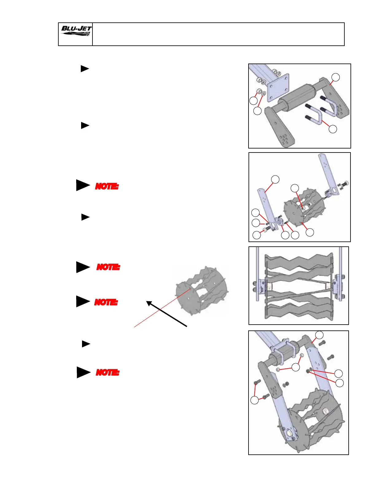
1. Attach (2) (AM7568) StripTill
torsion spring assembly
to rear of row mounting with
(15) (BP3300) 5/8” x 2-1/2” x
4” u-bolts, (9) (BP3039) 5/8”
lock washers and (8)
(BP3038) 5/8” hex nuts.
2. Attach (4) (AP2144) bearing
1”, with/ange on (1) (AM2269)
StripTill basket mounting short
18-3/4” with (5) (BP3012)
7/16” x 1-1/2” hex cap screws,
(7) (BP3017) 7/16” lock washers
and (6) (BP3016) 7/16” hex
nuts. Do not tighten hex nuts
until the basket is installed.
Insert (13) (BP3199) 1”-8 x
2-1/2” hex cap screw into
both bearing arm assemblies.
3. Insert (3) (AM7615) StripTill
basket over 1” x 2-1/2” hex
cap screw. Install (16) (BP3446)
1” center dimple lock nut.
Place socket on 1” hex cap
screw and tighten.
Tighten bearing hex nuts.
4. Position chopper basket
assembly on torsion spring
assembly. Insert (12) (BP3126)
1/2” x 1-1/2” hex cap screws,
top and bottom. Secure top
pivot hex cap screws with (14)
(BP3244) 1/2” lock hex nuts.
Secure lower adjustable hex
cap screws with (11) (BP3043)
1/2” lock washers and (10)
(BP3042) 1/2” hex nuts. Hex
nuts may be tightened.
(Diagram shows a starting
position.)
Torsion Arm Assembly
Attaching
bearings
and
chopper
basket to
mounting
arms
Position
chopper
basket on
torsion
spring
assembly
Centering
chopper
basket
NOTE:
Bearing
lock collars
are not
used
Attaching
torsion
spring
assembly
15
2
8
9
NOTE:
Bearing
lock collars
not used
12
10
11
14
NOTE:
Insert the
basket
arms to the
inside of
the StripTill
torsion
spring (2)
Direction of Travel
NOTE:
If the basket
has an arrow
on the side
see diagram
2
4
1
3
5
7
6
13
16
 Loading...