Task Procedures Illustrations
150
LEGACY
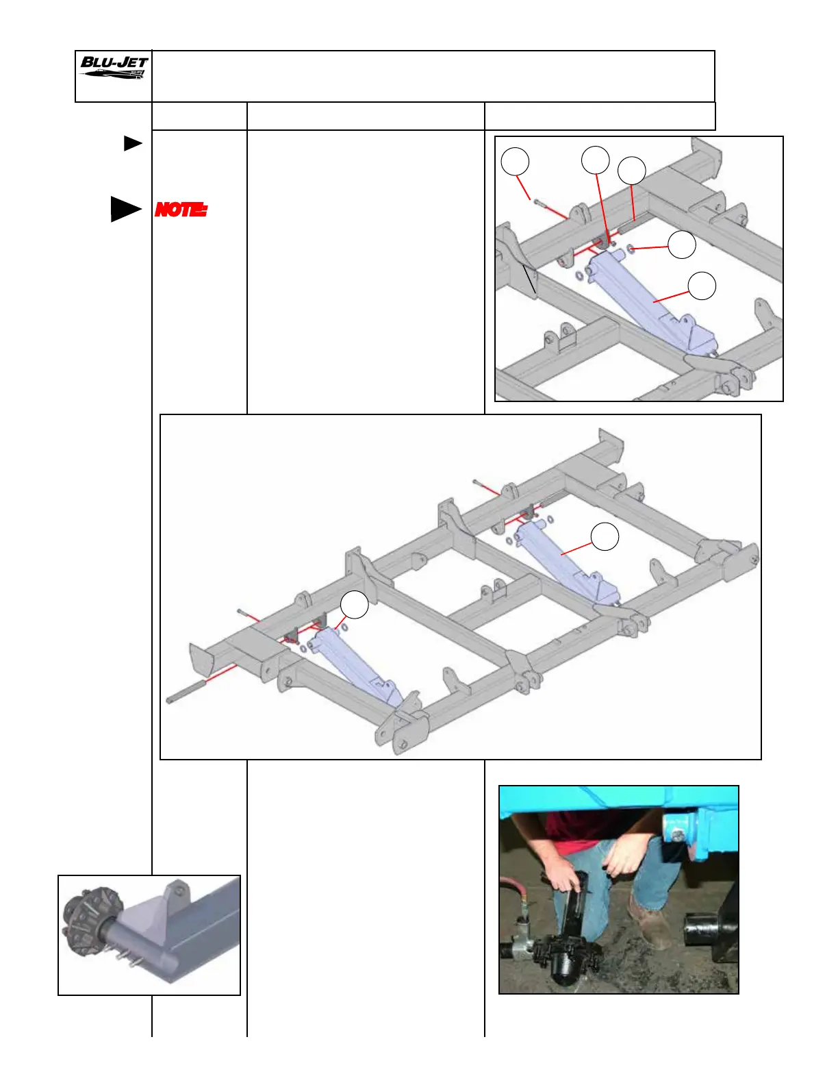
Single Wheel Center Lift Assembly
Mounting
single
wheel legs
NOTE:
Left-hand
and
right-hand
as viewed
from the
rear
1. Mount (a) (AM6226) left-hand
wheel leg with 3” spindle loop
single and (b) (AM6227) right-
hand wheel leg with 3” spindle
loop single to main frame.
2. Insert (c) (BM3664) 1-3/4” x
16-3/4” pin into main frame
weldment. Place (d) (BP3205)
2-1/2” x 1-3/4”ID 10 GA.
machinery bushings on both
sides of wheel leg tube as pin
is inserted.
Secure pin with (e) (BP3135)
5/8” x 3-1/2” hex cap screw and
(f) (BP3375) 5/8” Nylock hex
nut.
a
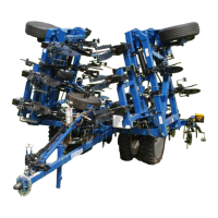
3. Remove paint from spindle
end. Place anti-seize on
spindle before inserting in
wheel leg loop.
4. Turn set screws out before
inserting spindle.
5. Insert spindle into wheel leg.
Position spindle to within 3” of
the wheel leg loop.
6. Tighten set screws and
remove lugs before mounting
tires.
Tractor Side
Right-hand side
from the rear
Left-hand side
from the rear
b
d
e
f
a
c