Task Procedures Illustrations
188
LEGACY
Primary Wing Left-hand Area of Bundle
Depth Control Assembly
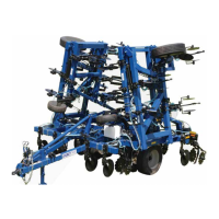
ATTACHING VALVE DEPTH CONTROL
ARM AND DEPTH CONTROL
PLUNGER STOP ARM
1. Insert (58) (BM3487) 1” x 7-3/4” pin into
bracket. Place (39) (AM6264) depth control
valve arm into bracket and insert (58) pin
into the rst side plate. Place (98) (BP3215)
1-1/2” OD x 1” ID machinery bushing over
pin end. Position (5) (AAM2928) depth
control plunger stop arm inside (39) bracket
and insert pin. Align the pin hole with the
mounting bracket and continue inserting pin.
Install second (98) machinery bushing as
pin is inserted. Secure pin with (87) (BP3115)
3/8” x 2” hex cap screw and (114) (CP2660)
3/8” hex lock nut.
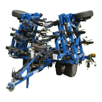
MOUNTING DEPTH CONTROL
ADJUSTMENT LINKAGE
1. Secure the round end of (6) (AAM2930)
depth control adjustment linkage to (40)
with (91) (BP3139) 3/4” x 2” hex cap screw
and (74) (BP3027) 3/4” hex lock nut.
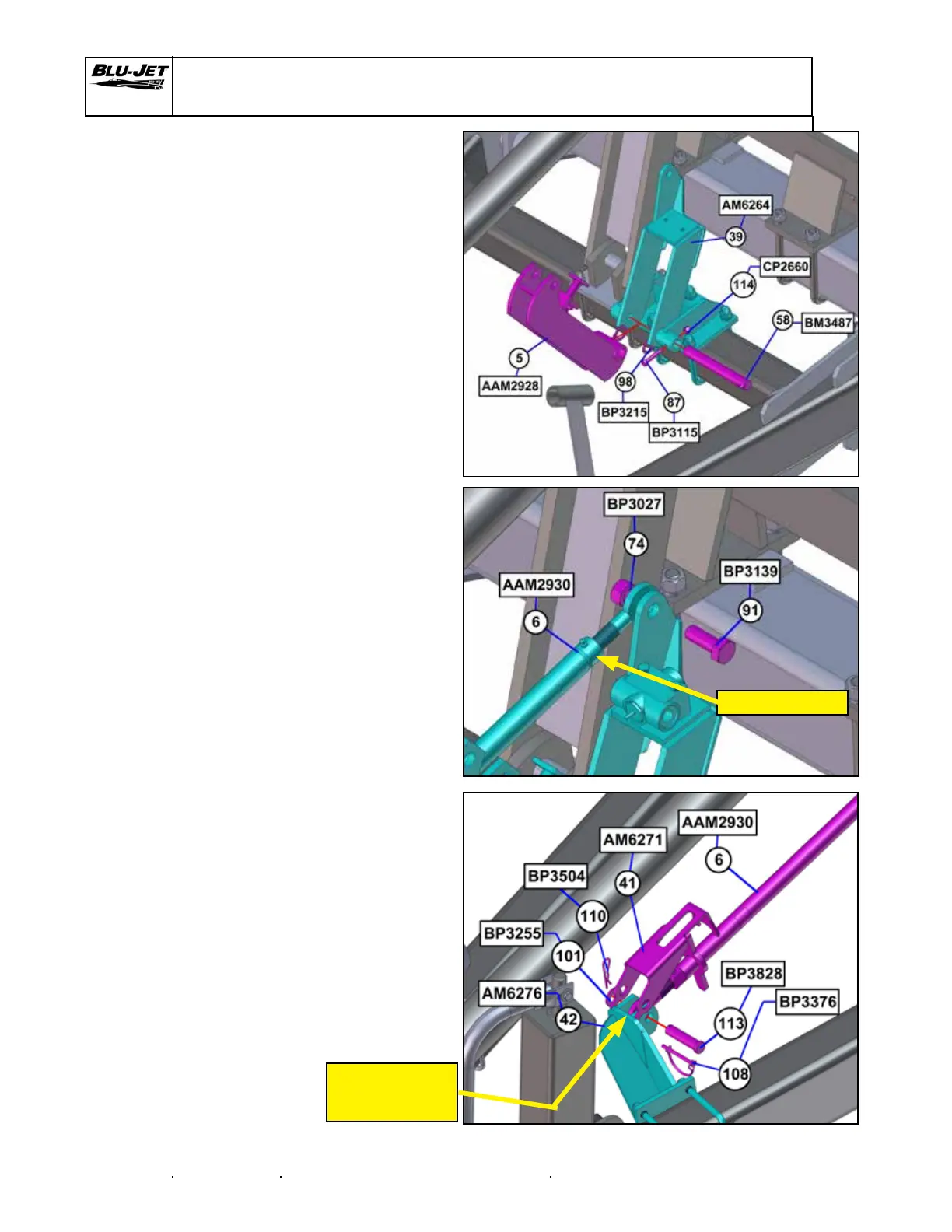
MOUNTING DEPTH CONTROL
ADJUSTMENT LINKAGE
1. Insert adjustment end of (6) (AAM2930)
depth control adjustment linkage in (42).
2. Place (41) (AM6271) depth control adjuster
latch over bracket and insert (113) (BP3828)
3/4” x 3”, placing (101) (BP3255) 3/4” at
washer on the outside of the latch.
Secure pin with (110) (BP3504) 1/8” hairpin
clip.
3. Lock, latch down with (108) (BP3376) 1/4” x 2”
wire retaining pin.
ROUND END
ADJUSTMENT
END
 Loading...