173
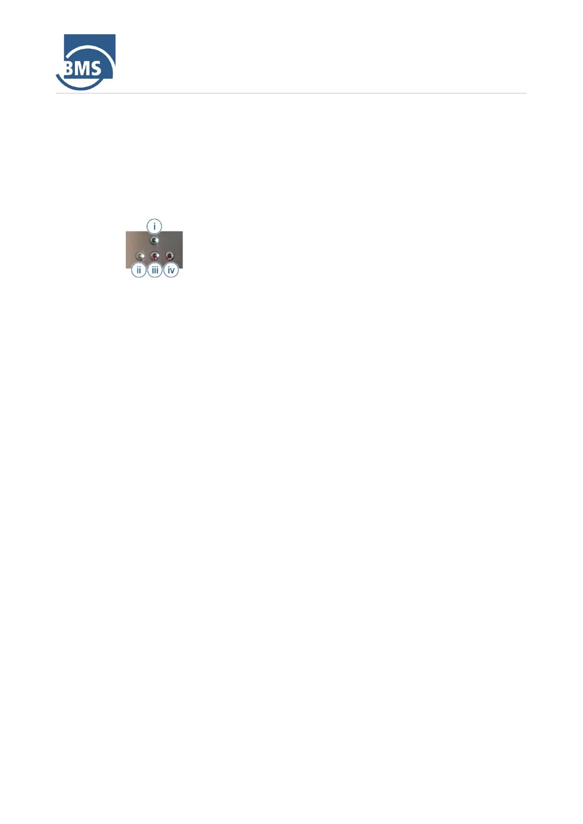
Main switch (1)
The control system is switched on via the main switch. Only when the control
is switched on can the machine be operated using the operating elements
on the outside of the machine
LED display (2)
The LED display shows the different operating states of the machine.
On/Off switch mixing unit (3)
This is a two-position switch. It switches the mixing unit in the mixing and
delivery vessel on/off.
Button Compressor on (4)
The delivery of the compressor is switched on via the button (4).
Pressure gauge compressor pressure (5)
The compressor pressure is displayed on the pressure gauge (4). This
pressure display can be used to monitor the delivery process. Possible
blockages can be recognised when the compressor pressure drops.
Boiler pressure gauge (6)
The pressure in the mixing and delivery vessel is displayed on the pressure
gauge (5). The quantity of upper and lower air can only be adjusted when
the pressure in the boiler is sufficient.
➢ When the lower air is open, the delivery pressure shown on the
pressure gauge corresponds to the vessel pressure.