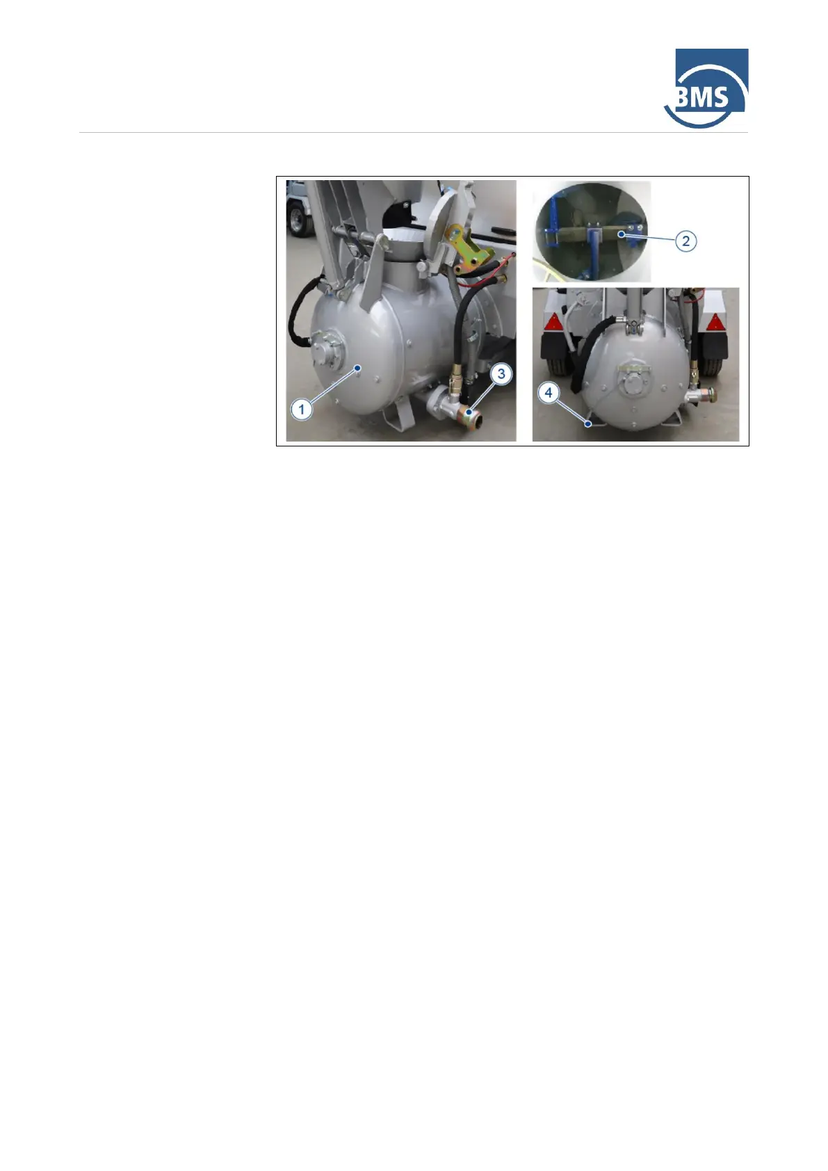
The building material is mixed in the mixing and delivery vessel (1), with the
pressure vessel being operated as a compulsory mixer.
The lateral openings on the vessel serve to accommodate the mixing shaft
(2), the mixing shaft bearing and the seal. The mixing shaft is equipped with
mixing blades for mixing the material to be conveyed (mix). The mixing shaft
blades convey the mix into the delivery hose, which is connected to the
connection (3), after pressure has been applied in the vessel. The delivery
capacity can be further increased by means of the selectable power mode.
The mixing shaft is driven by the diesel motor via a pulley and gearbox. The
mixing time is set individually via the automatic mixing time control before
starting the pumping operation (after switching on the machine).
At the rear of the mixing and delivery vessel there are two vessel feet (4),
which ensure that the BMS alpha
CR
stands firmly when the support wheel is
correctly adjusted.