787 Flight Crew Operations Manual
DO NOT USE FOR FLIGHT
Flight Instruments, Displays -
Controls and Indicators
Copyright © The Boeing Company. See title page for details.
10.10.34 D615Z003-TBC
Displayed with any altitude constraint directly beneath.
• dashed vertical line depicts lateral position
• during QFE operations, altitude constraints are shown in parentheses
below the QNH values
Displayed for approaches that have a designated approach angle:
• dashed line extends 10 NM for situational awareness
• anchored to the missed approach waypoint, not the runway
Displayed as triangle(s) on waypoint anchor line.
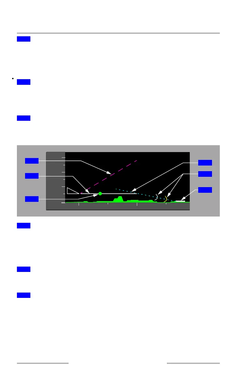
Vertical Situation Display (VSD) - Flight Path Background
Displays the selected vertical speed as a dashed target angle line when the MCP
V/S mode is selected.
Displays the flight path angle vector as a dashed target angle line when the MCP
FPA mode is selected.
Indicates current flight path angle as a function of vertical speed and groundspeed.
The length of the vector is fixed at one half of the VSD range.
Indicates where the airplane will achieve the FMC or MCP target speed:
• dot is blanked within 5 knots of target speed
• dot reappears if speed increases 10 knots or more faster than target speed
5
Waypoint ID and Anchor Line
6
FMC Approach Glidepath Angle Line
7
Altitude Constraint Symbol
1
MCP Selected Vertical Speed (V/S) or Flight Path Angle (FPA) Vector
2
Vertical Flight Path Vector
3
Range to Target Speed Dot (RTSD)
4
8
000
000
000
0
10
12
000
1
2
3
4
6
5
February 15, 2010