787 Flight Crew Operations Manual
DO NOT USE FOR FLIGHT
Flight Instruments, Displays -
Controls and Indicators
Copyright © The Boeing Company. See title page for details.
D615Z003-TBC 10.10.35
• dot is unfilled and placed at the end of the vertical flight path vector line if
the speed will not be achieved in the distance of the vertical flight path
vector line
• dot is unfilled and placed at the edge of the display along the vertical flight
path vector line if the speed will not be achieved within the display area
Displayed for approaches that do not have a designated approach angle:
• dashed line extends 10 NM for situational awareness
• anchored to the runway threshold
• for reference only, line may intersect terrain
Displayed on the FMC approach glidepath angle line or 3º reference line at 500
feet and 1,000 feet above field elevation.
Represents the selected runway. Runway length is scaled to the selected range.
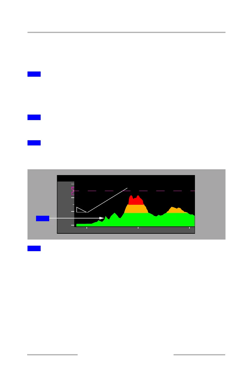
Vertical Situation Display (VSD) - Terrain Background
Represents the highest terrain within the enroute corridor:
• highest points of the terrain below and ahead of the airplane
• terrain is depicted so the true altitude separation between the airplane and
terrain is shown
• terrain behind the airplane is drawn equal to the terrain at the current
position
• VSD terrain uses the same color coding that is used to depict GPWS on the
lateral map:
• green: terrain 500 feet (250 feet if gear is down) or more below the
airplane
• amber: terrain from 250-500 below to 2,000 feet above the airplane
• red: terrain more than 2,000 feet above the airplane
4
3º Reference Line
5
Decision Gates
6
Runway
1
Terrain Profile Line
40200
8
4
12
000
000
000
000
10
000
1
February 15, 2010