Operating Instructions ACTIVE 06/07154
154 Operating Instructions ACTIVE 06/07
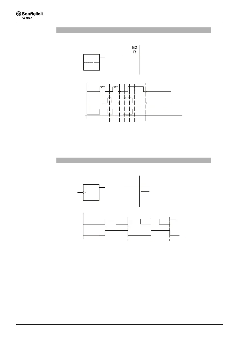
RS Flip-Flop
Parameter
Operation Mode Logic = 10
E1
S
Q
0
0
1
1
0
1
0
1
Q
n-1
0
1
0
Status
hold
reset
set
off
E1
E2
Q
S
R
Q
E1; S
E2; R
E1: set; E2:reset; Q: output
Set: Logic "1" at the set input will set output Q to logic "1".
Store: If a logic "0" is present at the S input, output Q remains unchanged.
Reset: If the R input is set to logic "1", output Q is set to logic "0".
Off: If both inputs are set to logic "1", output Q will be logic "0".
Toggle Flip-Flop
Parameter
Operation Mode Logic = 20
E1
Q
T
E1
T
Q
1
0–>1
1–>0
0
Q
Q
Q
n-1
n-1
n-1
Q
n-1
Status
hold
output invers (toggle)
hold
hold
Q
E1; T
E1: clock input T; Q: output
The T flip-flop changes its output state with each positive clock edge at input 1 (clock
pulse input T). In all other signal states of the clock input (static logic "0" or logic "1"
or negative clock edge), the output signal remains unchanged.
Note: Input 2 is deactivated in this configuration. A parameterization of input
2 via the corresponding parameters will be have no effect for this rea-
son.
 Loading...


