EasyManua.ls Logo

BONFIGLIOLI act 401 User Manual

BONFIGLIOLI act 401
218 pages
To Next Page IconTo Next Page
To Previous Page IconTo Previous Page
Page #157 background imageLoading...
Page #157 background image
Operating Instructions ACTIVE06/07 155
06/07 Operating Instructions ACTIVE 155
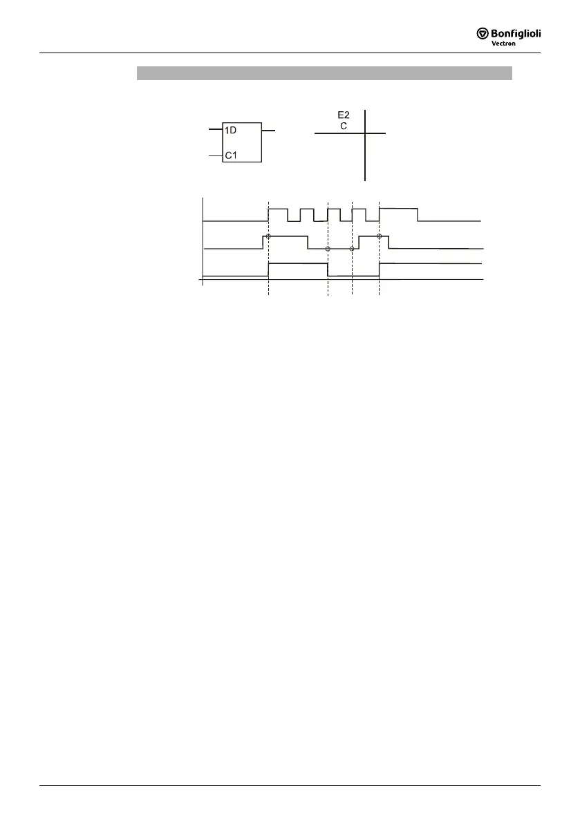
D Flip-Flop
Parameter
Operation Mode Logic = 30
Q
E2; C
E1; D
E1; D
E2; C
Q
E1
D
Q
0
1
0
1
0
0
0–>1
0–>1
Q
n-1
Q
0
1
n-1
Status
hold
sample
hold
sample
E1: data input D; E2: clock input C; Q: output
If logic "0" is present at input 2 (clock input C), the previous logic state is maintained
at the output independent of the status of input 1 (data input D).
If a positive clock edge is received at clock pulse input C, the signal present at data
input D is transmitted to the output. The output maintains its state Q
n-1
until the next
positive clock edge is received.
If a negative clock edge is received, the output signal remains unchanged.

Table of Contents

Question and Answer IconNeed help?

Do you have a question about the BONFIGLIOLI act 401 and is the answer not in the manual?

BONFIGLIOLI act 401 Specifications

General IconGeneral
BrandBONFIGLIOLI
Modelact 401
CategoryDC Drives
LanguageEnglish

Summary

General Information about the Documentation

Quick Start Guide

Basic steps for installation and commissioning.

Operating Instructions

Details all functions and parameters for adapting the inverter.

Application Manual

Supplements documentation for installation and commissioning.

Installation Instructions

Information on installing optional components.

1 General Safety Instructions and Information on Use

1.1 General Information

Information about DC-link circuit, high voltage, and safety.

1.2 Purpose of the Frequency Inverters

Electrical drive components for industrial plants and machines.

1.3 Transport and Storage

Guidelines for proper transport and storage of devices.

1.4 Handling and Installation

Precautions for handling and installing inverters.

1.5 Electrical Connection

Safety and compliance for electrical connections.

1.6 Information on Use

Guidelines for safe operation and usage of the inverter.

1.7 Maintenance and Service

Unauthorized interventions can lead to injury or damage.

2 Scope of Supply

2.1 ACT 201 (up to 3.0 kW) and ACT 401 (up to 4.0 kW)

Details the scope of delivery for specific models.

2.2 ACT 201 (4.0 up to 9.2 kW) and ACT 401 (5.5 up to 15.0 kW)

Lists items included in the scope of delivery for these models.

2.3 ACT 401 (18.5 up to 30.0 kW)

Details the scope of delivery for these specific ACT 401 models.

2.4 ACT 401 (37.0 up to 65.0 kW)

Lists the standard delivery components for ACT 401 models in this power range.

2.5 ACT 401 (75.0 up to 132.0 kW)

Specifies the scope of supply for high-power ACT 401 inverters.

3 Technical Data

3.1 General technical data

Covers CE conformity, EMC directive, UL approval, ambient conditions, and functions.

3.2 Technical data of control electronics

Details technical specifications for control terminals X210A and X210B.

3.3 ACT 201 (0.55 up to 3.0 kW, 230 V)

Provides technical data for ACT 201 models in the specified power and voltage range.

3.4 ACT 201 (4.0 up to 9.2 kW, 230 V)

Details technical specifications for ACT 201 models within this power and voltage range.

3.5 ACT 401 (0.55 up to 4.0 kW, 400 V)

Technical data for ACT 401 models in the 400V range, 0.55-4.0 kW.

3.6 ACT 401 (5.5 up to 15.0 kW, 400 V)

Technical specifications for ACT 401 models, 400V, 5.5-15.0 kW.

3.7 ACT 401 (18.5 up to 30.0 kW, 400 V)

Technical data for ACT 401 models in the 400V range, 18.5-30.0 kW.

3.8 ACT 401 (37.0 up to 65.0 kW, 400 V)

Technical specifications for higher power ACT 401 models (400V).

3.10 Operation Diagrams

Graphical representations of derating based on altitude, temperature, and voltage.

4 Mechanical Installation

4.1 ACT 201 (up to 3.0 kW) and ACT 401 (up to 4.0 KW)

Vertical mounting instructions and dimensions for smaller models.

4.2 ACT 201 (4.0 up to 9.2 kW) and ACT 401 (5.5 up to 15.0 kW)

Mounting details and dimensions for mid-range ACT 201/401 models.

4.3 ACT 401 (18.5 up to 30.0 kW)

Mechanical installation and dimensional data for ACT 401 models in the 18.5-30.0 kW range.

4.4 ACT 401 (37.0 up to 65.0 kW)

Mounting instructions and dimensions for ACT 401 models, 37.0-65.0 kW.

4.5 ACT 401 (75.0 up to 132.0 kW)

Mechanical installation details and dimensions for the largest ACT 401 models.

5 Electrical Installation

5.1 EMC Information

Measures to minimize electromagnetic interference during installation.

5.2 Block diagram

Illustrates the functional connections of control terminals and outputs.

5.3 Optional Components

Information on installing control units and communication/expansion modules.

5.4 Connection of the device

Guidelines for dimensioning conductor cross sections.

5.4.2 Mains Connection

Instructions for selecting mains fuses and cable cross-sections.

5.4.3 Motor connection

Recommendations for connecting motor cables, including length and filters.

5.4.4 Connection of a Brake Resistor

Details on connecting brake resistors and safety precautions.

5.5 Connection of the construction sizes

Mains power connection details for ACT 201/401 up to 4.0 kW.

5.5.2 ACT 201 (4.0 up to 9.2 kW) and ACT 401 (5.5 up to 15.0 kW)

Mains power connection for ACT 201/401, 4.0-15.0 kW.

5.5.3 ACT 401 (18.5 up to 30.0 kW)

Mains power connection for ACT 401, 18.5-30.0 kW.

5.5.4 ACT 401 (37.0 up to 65.0 kW)

Mains power connection for ACT 401, 37.0-65.0 kW.

5.5.5 ACT 401 (75.0 up to 132.0 kW)

Mains power connection for ACT 401, 75.0-132.0 kW.

6 Control Unit KP500

6.1 Menu Structure

Arrangement of menus and functions on the control unit.

6.2 Main Menu

Overview of the four main menu branches for navigation.

6.3 Actual Value Menu (VAL)

Displays various actual values based on configuration and installed options.

6.4 Parameter Menu (PARA)

Allows configuration of parameters during guided commissioning.

6.5 Copy Menu (CPY)

Copies parameter values to/from non-volatile memory for easy re-parameterization.

6.5.4 Selecting the Destination

Specifies the target location for copied parameter data.

6.6 Read data from the KP 500 control unit

Enables transmission of data from KP 500 to the frequency inverter.

6.6.2 Transfer data

Details the process of transmitting files from the control unit to the frequency inverter.

6.7 Control Menu (CTRL)

Enables control of the drive via the control unit.

6.8 Controlling the Motor via the Control Unit

Controls the motor based on selected operation mode and parameter settings.

Motor potentiometer function Pot

Adjusts output frequency using arrow keys via the control unit.

Function Motorpoti (KP) inP

Adjusts output frequency using arrow keys, linked to reference values.

7 Commissioning of the Frequency Inverter

7.1 Switching on Mains Voltage

Checks connections and power-up sequence.

7.2 Setup Using the Control Unit

Guided procedure to determine parameter settings for application.

7.2.1 Configuration

Determines assignment of inputs/outputs and software functions for drive control.

7.2.2 Data Set

Enables selection of one of four data sets for parameter storage.

7.2.3 Motor Type

Sets motor properties for control functions based on table values.

7.2.4 Machine Data

Entry of motor data from type plate for plausibility check.

7.2.5 Plausibility check

Verifies entered machine data and checks for warnings or errors.

7.2.6 Parameter identification

Measures machine data and enters it automatically for parameterization.

7.3 Check direction of rotation

Verifies actual direction of rotation against reference value.

7.4 Speed sensor

Configuration for connecting and evaluating speed sensors.

7.4.1 Speed sensor 1

Configuration parameters for speed sensor 1.

7.4.2 Speed sensor 2

Configuration parameters for speed sensor 2 via expansion module.

7.5 Set-up via the Communication Interface

Parameter setting and commissioning via optional interfaces.

8 Inverter Data

8.1 Serial Number

Identifies device type, fabrication data, and serial number.

8.2 Optional Modules

Details recognition of plug-in modules and their designations.

8.3 Inverter Software Version

Indicates firmware version and software key.

8.4 Set Password

Protects parameter access by setting a password.

8.5 Control Level

Defines the scope of functions for parameterization.

8.6 User Name

Allows entering plant or machine designation.

8.7 Configuration

Determines assignment of inputs/outputs and software functions for drive control.

9 Machine Data

9.1 Rated Motor Parameters

Sets motor parameters according to nameplate or data sheet.

9.2 Further motor parameters

Details parameters like stator resistance and leakage coefficient.

9.2.3 Magnetizing Current

Sets magnetizing current for sensorless field-oriented control.

9.2.4 Rated Slip Correction Factor

Adjusts slip based on rotor time constant and temperature.

9.3 Internal values

Parameters used for internal processing of motor data.

9.4 Speed sensor 1

Configuration for incremental speed sensor connection and evaluation.

9.4.1 Operation mode speed sensor 1

Selects operation mode for speed sensor 1 evaluation.

10 System Data

10.1 Actual Value System

Monitors drive via actual value system and applies a factor.

10.2 Volume Flow and Pressure

Parameterizes factors for monitoring volume flow and pressure.

11 Operational Behavior

11.1 Starting Behavior

Parameterizes starting and stopping behavior of the 3-phase machine.

11.1.1 Starting Behavior of Sensorless Control System

Configures starting behavior for sensorless control via operation modes.

11.1.1.1 Starting Current

Sets starting current for heavy starting applications.

11.1.1.2 Frequency Limit

Sets frequency limit for permanent operation below the limit.

11.1.2 Flux Formation

Controls magnetization and current impression for field-oriented control.

11.2 Stopping Behavior

Defines machine stopping behavior using digital logic signals.

Stopping Behavior 0 (Free stopping)

Inverter disabled, drive coasts freely.

Stopping Behavior 1 (Stop + Switch off)

Drive standstill, inverter disabled after holding time.

Stopping Behavior 2 (Stop + Hold)

Drive standstill, permanently supplied with current.

11.2.1 Switch-Off Threshold

Defines frequency for recognizing drive standstill.

11.2.2 Holding Time

Considers holding time in stopping behaviors for motor heating.

11.3 Direct current brake

Implements direct current brake for stopping behaviors and search run.

11.4 Auto Start

Accelerates drive after mains voltage connection with controller enabled.

11.5 Search Run

Synchronizes motor speed to rotating drive without overcurrent fault.

11.6 Positioning

Controls positioning based on distance or angle via reference signals.

11.6.1 Reference Positioning

Defines positioning distance relative to reference signal for application accuracy.

11.6.2 Axle Positioning

Performs positioning based on reference orientation and speed sensor feedback.

12 Error and warning behavior

12.1 Overload Ixt

Monitors admissible load behavior based on switching frequency and ambient conditions.

12.2 Temperature

Monitors heat sink and inside temperatures to prevent fault switch-off.

12.3 Controller Status

Indicates controller intervention and operating behavior via status messages.

12.4 IDC Compensation Limit

Compensates DC component in output current due to unbalances.

12.5 Frequency Switch-Off Limit

Sets maximum permissible output frequency to prevent inverter switch-off.

12.6 Motor Temperature

Monitors motor temperature using digital inputs for application-specific behavior.

12.7 Phase Failure

Monitors phase failure to prevent damage to inverter and drive components.

12.8 Automatic Error Acknowledgment

Enables automatic acknowledgment of specific faults without user intervention.

13 Reference Values

13.1 Frequency Limits

Defines output frequency and speed setting ranges via min/max parameters.

13.3 Percentage Value Limits

Sets percentage ranges for reference values via min/max parameters.

13.4 Frequency Reference Channel

Connects various functions for defining reference frequency via hardware assignment.

13.4.1 Block Diagram

Describes software switch positions for selected reference frequency sources.

13.5 Reference Percentage Channel

Combines signal sources for defining reference values with percentage scaling.

13.6 Fixed Reference Values

Parameterizes fixed frequencies or percentages based on configuration.

13.6.1 Fixed Frequencies

Defines four fixed frequencies selected via change-over modes.

13.6.3 Fixed Percentages

Defines four percentage values selected via change-over modes.

13.7 Frequency ramps

Determines how fast frequency changes after start, stop, or brake commands.

13.8 Percentage Value Ramps

Scales reference value change using percentage ramps.

13.9 Block Frequencies

Fades out reference frequencies to avoid system resonance points.

13.10 Motor Potentiometer

Controls motor speed using digital signals or KP 500 control unit keys.

13.10.3 Controlling the Motor via the Control Unit

Controls motor speed using KP 500 keys and reference value sources.

14 Control Inputs and Outputs

14.1 Multi-function input MFI1

Configurable input for voltage, current, or digital signals for various functions.

14.1.1 Analog Input MFI1A

Configured for analog reference value source (0-10V or 0-20mA).

14.1.1.2 Scaling

Maps analog input signal to configurable characteristic using frequency/percentage limits.

14.1.1.3 Tolerance Band and Hysteresis

Adapts analog input characteristic with sign change of reference value.

14.1.1.4 Filter Time Constant

Sets time constant for averaging analog input signal via low-pass filter.

14.1.1.5 Error and warning behavior

Monitors analog input signal and issues warnings or shut-downs.

14.2 Multi-function output MFO1

Configurable output for digital, analog, or repetition frequency signals.

14.2.1 Analog Output MFO1A

Configured for pulse-width modulated output signal with adjustable voltage range.

14.2.2 Frequency Output MFO1F

Provides 24V output signal as repetition frequency based on operation mode.

14.3 Digital Outputs

Links digital outputs and relay output to various functions based on configuration.

14.3.1 Setting Frequency

Activates digital output when stator frequency exceeds a set value.

14.3.2 Reference value reached

Generates message when actual frequency/percentage reaches reference value.

14.3.3 Flux Formation Ended

Activates digital output when flux formation is completed.

14.3.4 Open brake

Enables activation of a brake unit via digital control output.

14.3.5 Current Limitation

Links digital outputs to intelligent current limits for power reduction.

14.3.6 External Fan

Controls external fan based on controller release, start signals, or temperature.

14.3.7 Warning Mask

Sets logic signals for monitoring functions to combine warnings.

14.4 Digital Inputs

Assigns control signals to software functions, allowing flexible use.

14.4.1 Start command

Links start parameters to digital inputs or internal logic for drive acceleration.

14.4.2 3-Wire-Control

Controls drive via digital pulses for start, stop, and direction.

14.4.3 Error Acknowledgment

Acknowledges faults via parameter or logic signal.

14.4.4 Timer

Selects time functions via operation modes and links logic signals.

14.4.5 Thermo-contact

Monitors motor temperature via digital input and linked operation modes.

14.4.6 n-/M-Control Change-Over

Switches between speed and torque control in field-oriented configurations.

14.4.7 Data Set Change-Over

Stores parameter values in four data sets for operation point adaptation.

14.4.8 Fixed Value Change-Over

Specifies reference values via fixed frequencies or percentages based on configuration.

14.4.9 Motor Potentiometer

Defines motor potentiometer behavior based on operation mode.

14.5 Function Modules

Links timer functions for time-controlled digital signals.

14.5.1 Timer

Links timer functions for time-controlled digital signals.

14.5.1.1 Time Constant

Sets time constant for averaging analog input signal via low-pass filter.

14.5.3 Logic Modules

Links external and internal digital signals using combinatory or sequential logic.

14.5.2 Comparator

Performs comparisons of actual values with percentage-adjustable fixed values.

15 V/f - Characteristic

15.1 Dynamic Voltage Pre-Control

Accelerates control behavior by adding calculated voltage pre-control.

16 Control Functions

16.1 Intelligent current limits

Sets current limits to avoid inadmissible loading and prevent fault switch-off.

16.2 Voltage controller

Monitors DC link voltage and controls it to a set limit value.

16.3 Technology Controller

PI controller for process control like pressure, flow, or speed.

16.4 Functions of Sensorless Control

Additional functions supplementing V/f characteristic for sensorless control.

16.4.1 Slip compensation

Compensates load-dependent speed difference using current measurement.

16.4.2 Current limit value controller

Reduces output frequency during acceleration to prevent overload.

16.5 Functions of Field-Orientated Control

Control modes based on cascade control and machine model calculation.

16.5.1 Current Controller

Controls flux-forming and torque-forming current components.

16.5.2 Torque Controller

Limits speed by reaching reference torque until frequency limits are met.

16.5.3 Speed controller

Selects actual speed source and operation mode for speed controller.

16.5.3.1 Limitation of Speed Controller

Limits output signal of speed controller (current, torque, power).

16.5.3.2 Limit Value Sources

Links analog input or fixed values to limit speed controller.

16.5.4 Acceleration Pre-Control

Reduces drive system reaction time by pre-controlling acceleration.

16.5.5 Field Controller

Controls flux-forming current component using optimized parameters.

16.5.5.1 Limitation of field controller

Limits output signal of modulation controller via reference flux parameters.

16.5.6 Modulation Controller

Automatically adapts output value to machine behavior in basic and field weakening areas.

17 Special Functions

17.1 Pulse Width Modulation

Reduces motor noises by changing switching frequency.

17.2 Fan

Sets switch-on temperature for heat sink fan and controls external fans.

17.3 Bus controller

Integrates inverters into automation systems via communication options.

17.5 Motor Circuit Breaker

Protects motor and cable against overload and disconnects on short-circuit.

17.6 V-belt Monitoring

Monitors load behavior and connection via V-belt system.

17.7 Functions of Field-Orientated Control

Control functions for field-orientated control, adaptable via special functions.

17.7.1 Motor Chopper

Adapts generator energy to heat in the connected three-phase machine.

17.7.2 Temperature Adjustment

Adjusts rotor time constant based on motor temperature measurement.

17.7.3 Encoder Monitoring

Monitors speed sensor signal, track signal, and division marks for failures.

18 Actual Values

18.1 Actual Values of the Frequency Inverter

Displays application-specific actual values based on configuration and expansion cards.

18.2 Actual Values of the Machine

Displays electrical control variables and actual values of the machine/system.

18.3 Actual Value Memory

Stores actual values for operating behavior assessment and maintenance.

18.4 Actual Values of the System

Calculates system actual values based on parameterized system data.

18.4.1 Actual Value System

Monitors drive via actual value system and applies a factor.

19 Error Protocol

19.1 Error List

Stores last 16 fault messages chronologically.

20 Operational and Error Diagnosis

20.1 Status Display

Provides operating point information via green/red LEDs and display elements.

20.2 Status of Digital Signals

Displays status of digital inputs/outputs for checking control signals.

20.3 Controller Status

Establishes active control functions and displays controller codes.

20.4 Warning Status

Displays current warnings as messages and sums of individual codes.

21 Parameter List

21.1 Actual Value Menu (VAL)

Lists actual values, their units, display ranges, and corresponding chapters.

21.2 Parameter Menu (PARA)

Lists parameters by menu branch, description, unit, setting range, and chapter.

Related product manuals