Installation
EN
150 bora.com
Connection Fuse protection Minimum cross-
section
Three-phase
connection
3 x 16 A 2.5mm²
Two-phase
connection
2 x 16 A 2.5mm²
One-phase
connection
1 x 32 A 4mm²
Tab.9.2
Fuse protection and minimum cross-section
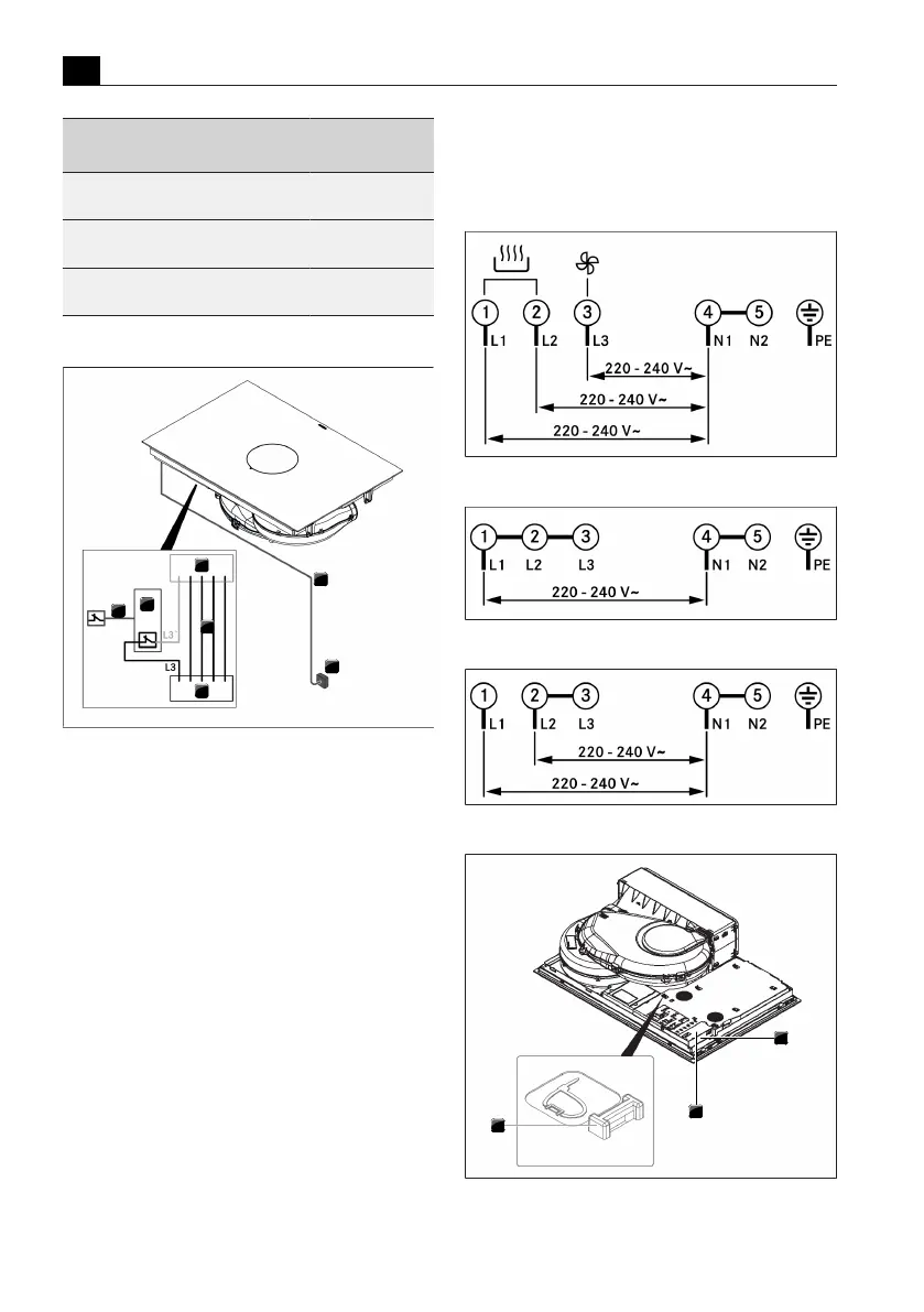
Fig.9.42
Connection diagram with external switch contact
[1]
Cooktop and cooktop extractor power supply cable
[2]
Power supply
[3]
Cooktop and cooktop extractor power supply
[4]
Switch relay
[5]
Switch connection S1 and switch relay
[S1]
External switch contact
u
Connect the power supply cable to the power supply
of the appliance in accordance with the relevant
connection diagram (see Fig. Connection diagram or
underside of appliance).
u
For a single-phase or two-phase connection, connect
the relevant contacts using the bridge provided (in
scope of delivery).
u
Secure the connection cable with the strain relief
clamp (in scope of delivery).
u
Close the power supply housing with the power
supply cover (in scope of delivery).
u
Lay the connection cable along the mounting eyes
with the help of the cable ties (in scope of delivery).
u
Ensure that the cable is not trapped or damaged and
is not able to come into contact with any hot areas
on the cooktop.
u
Check that installation has been carried out correctly.
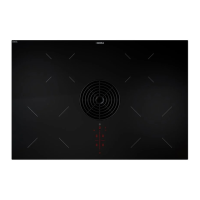
Fig.9.43
Connection diagram for 3-phase connection
Fig.9.44
Connection diagram for 1-phase connection
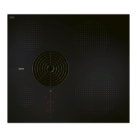
Fig.9.45
Connection diagram for 2-phase connection
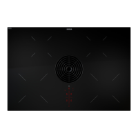
Fig.9.46
Electrical connections of the cooktop