CLUTCH
KUKJE MACHINERY CO., LTD.
42
4. CHECKING, DISASSEMBLING AND SERVICING
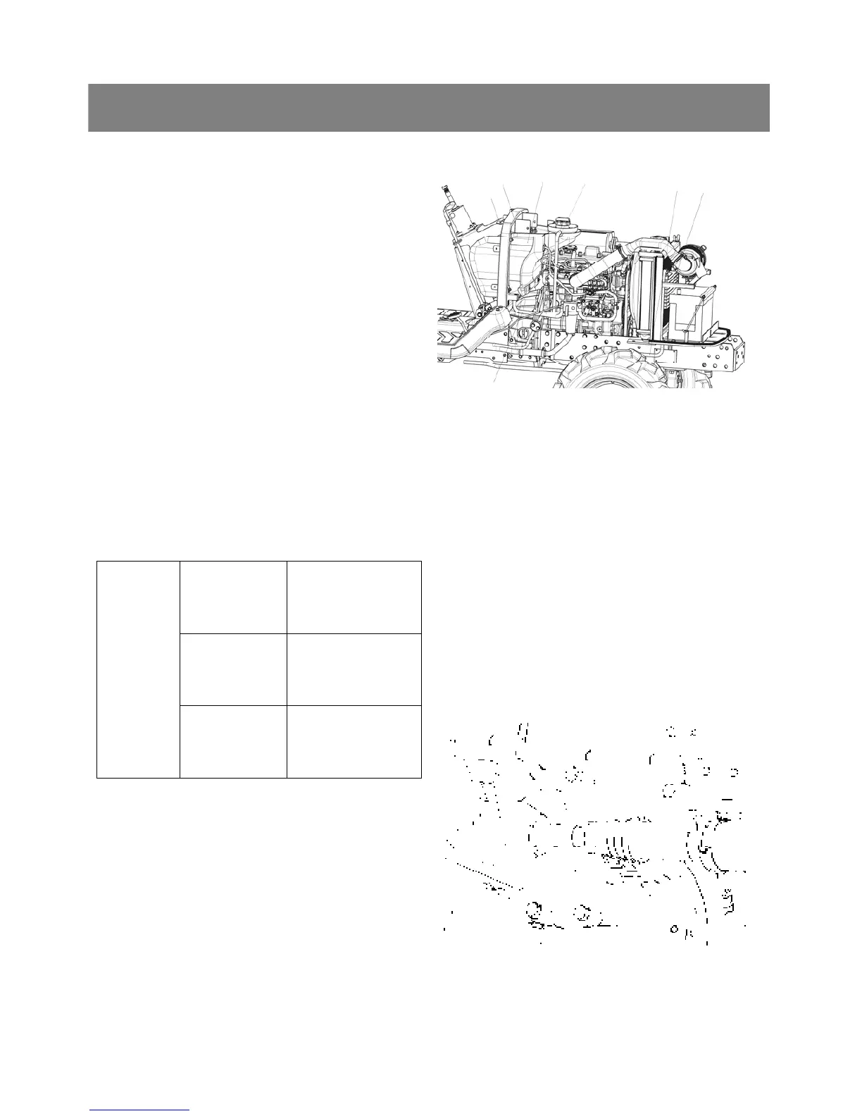
*. PART NAME
1) Fuel hose 2) Fuel tank frame
3) Fuel tank 4) Oil cooler
5) Overflow hose 6) Hydraulic hose
7) Steering bracket
< Fuel tank >
1. Disconnect the fuel house(1) at the fuel filter
side, then drain fuel completely.
2. Disconnect the hazard unit, controller, starter
relay and regulator connectors and remove the
lead wire for fuel gauge.
3. Disconnect the overflow hoses(5) of fuel line.
4. Loosen the steering bracket(7).
5. Remove the tank frame(2) with fuel tank(3).
6. Remove the battery.
7. Disconnect the hydraulic pipes(6) and remove
the battery stay with oil cooler(4).
▶ NOTE
1) For fastening hydraulic pipe nut, use two
wrenches. Hold the fitting with a wrench, turn
the pipe nut with another wrench to avoid
damage at fitting installed part.
Delivery pipe
nut for HST
34.3 to 39.2 Nm
3.5 to 4.0 kgfm
25.3 to 28.9 ft-lbs
Oil cooler
pipe nut
50.0 to 57.9 Nm
5.1 to 5.9 kgfm
36.9 to 42.8 ft-lbs
Tightening
Torq ue
Delivery pipe
nut for power
steering
64.7 to 75.5 Nm
6.6 to 7.7 kgfm
47.9 to 55.3 ft-lbs
< Propeller shaft cover and coupling >
1. Loosen the clamp and slide the propeller shaft
cover(1) to the rear.
2. Ta p out the spring pin(2) and then slide the
coupling(3) to the rear.
▷ Reassembling
Apply grease to the spline of the propeller shaft
and coupling.
*. PART NAME
1) Propeller shaft cover 2) Spring pin
3) Coupling
(1)
(7)
(2)
(3)
(5)
(6)
(4)