TRANSMISSION
KUKJE MACHINERY CO., LTD.
84
5. CHECKING, DISASSEMBLING AND SERVICING
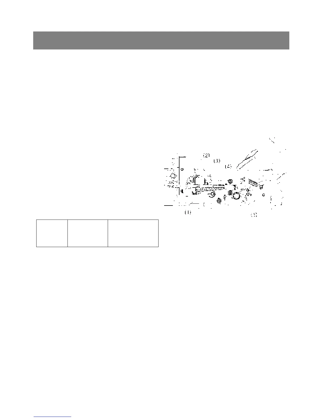
*. PART NAME
1) Brake rod RH
2) Speed control rod screw
3) Speed control rod assembly
4) Damper
5) HST pedal
< Propeller shaft cover and coupling >
-. Reference the page 78.
< Universal joint and bearing holder >
-. Reference the page 79.
< HST Pedal >
1. Remove the brake rod RH(1).
2. Remove the damper(4) and speed control rod
assembly(3).
3. Remove the HST pedal(5).
4. Remove the speed control rod screw(2) from the
neutral holder.
▷ Reassembling
9 Apply liquid lock to the speed control rod
screw(2).
Tightening
torque
Speed control
rod screw
39.2 to 44.1 Nm
4.0 to 4.5 kgfm
28.9 to 32.5 ft-lbs