6. Service Procedures PreciseFlex 100 Robot
Wiring for Pneumatic Gripper Part Number: 603988 Rev. A
For this GIO, it is configured (see Table 6-2 ) as “GIO6” so the 8 outputs will be addressed as
600013-600020 and the 12 inputs will be addressed as 610001-6100012.
To specify a GIO's general-purpose
digital I/O signal from the master
controller, multiply the GIO's network
node number (not the GIO's unit
number) by 100000 and add the I/O
signal’s number. For example, to
access a GIO board configured as the
2nd or nth network node, add 200000
or 100000*n to the signal number.
Node
Signal Offset
GIO Module
Outputs (8) Inputs (12)
2 200000 200013-200020 210001-210012
n 100000*n n00013-n00020 n10001-n10012
Table 6-2: GIO Configuration
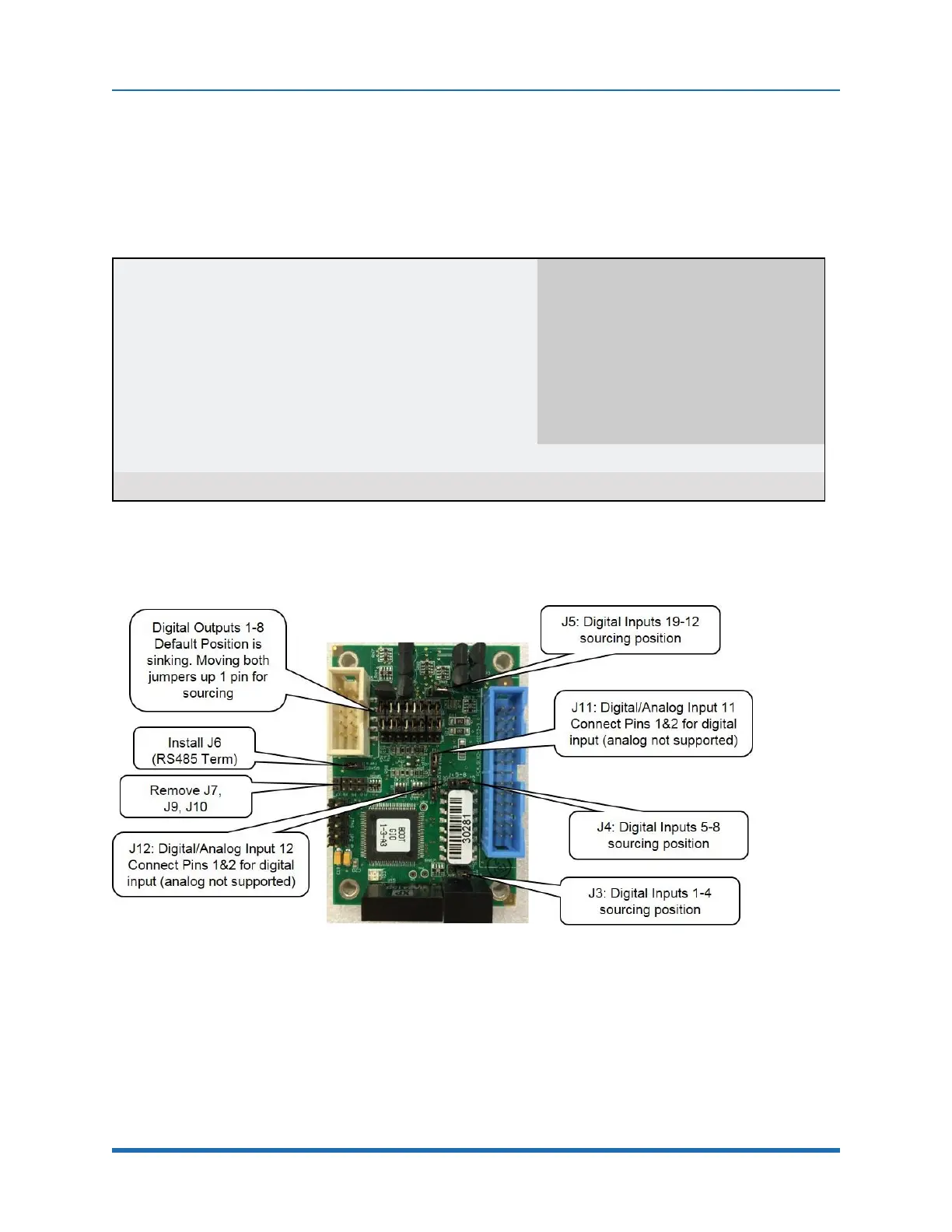
See jumpers in Figure 6-5. Inputs and outputs are 24VDC with outputs limited to 100 mA. For pin
assignments on the 25-pin Dsub, see "RS485 Remote IO Module (GIO)".
Figure 6-5: GIO Jumpers, GIO_6
110
Copyright © 2023 Brooks Automation, Inc.