Section 03 ENGINES
Subsection 06 (BOTTOM END)
Crankshaft Bearing Installation
CAUTION: Never reinstall a bearing that has
been removed.
Slide in the inner PTO bearing with the integrated
seal facing crankshaft. Push bearing to end posi-
tion.
A32CAVA
NOTE: Heated bearings will slide onto the crank-
shaft. If required, push with a steel tube on the
inner ring of the bearing. Pay special attention
to correct positioning of the drive pins and/or
retaining discs.
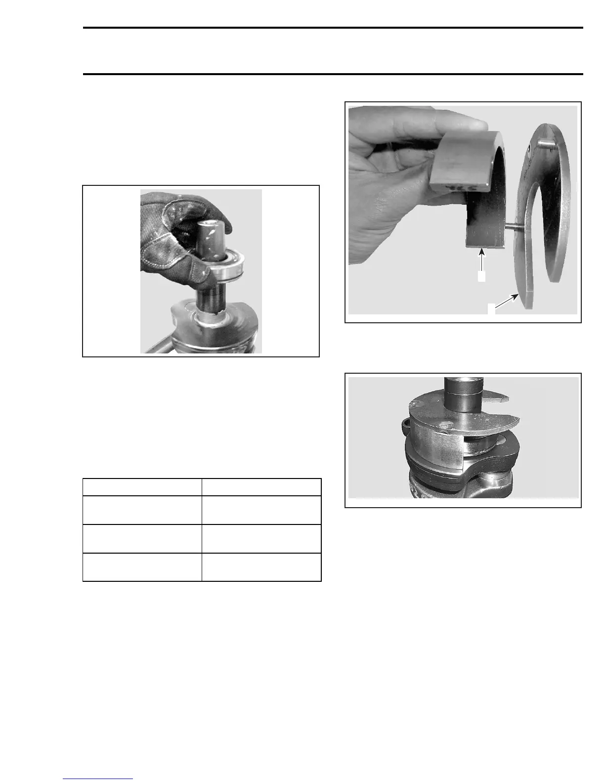
Install retaining discs.
Install support plate (P/N 529 035 976) with appro-
priate distance gauge; refer to following table.
TOOL ENGINE
Distance gauge
(P/N 529 035 966)
593
Distance gauge
(P/N 529 035 967)
593 HO
Distance gauge
(P/N 529 035 968)
593 HO SDI and 793 HO
A32CBCA
2
1
1. Support plate
2. Distance gauge
Install bearing locator tool.
A32CAWA
Slide in the heated outer PTO bearing onto the
crankshaft until it contacts the distance gauge.
Slide-in the first MAG bearing with the integrated
seal facing crankshaft. Push bearing to the bot-
tom with pusher, using a rubber hammer.
mmr2005-073 125