Section 08 DRIVE SYSTEM
Subsection 02 (DRIVE PULLEY)
Lever, Nut and Cotter Pin
NOTE: While installing lever no. 29 make sure that
the curved sides of the levers are outwards as
shown.
A32D1ZA
Always install lever assemblies so that cotter pins
no. 30 are on the shown side. Besides install cot-
ter pin head on top when lever is sat at bottom of
sliding half. Bend cotter pin ends to sit perfectly
against lever.
WARNING
Whenever replacing centrifugal levers, al-
waysreplaceall3atthesametime. Other-
wise, drive pulley misbalancing will occur
because of levers difference.
CAUTION: Lever assemblies must be installed
so that cotter pins are on the same side.
793 HO Engine Equipped Models Only
A16D0BA
1
2
TYPICAL
1. Head on top
2. All on the same side
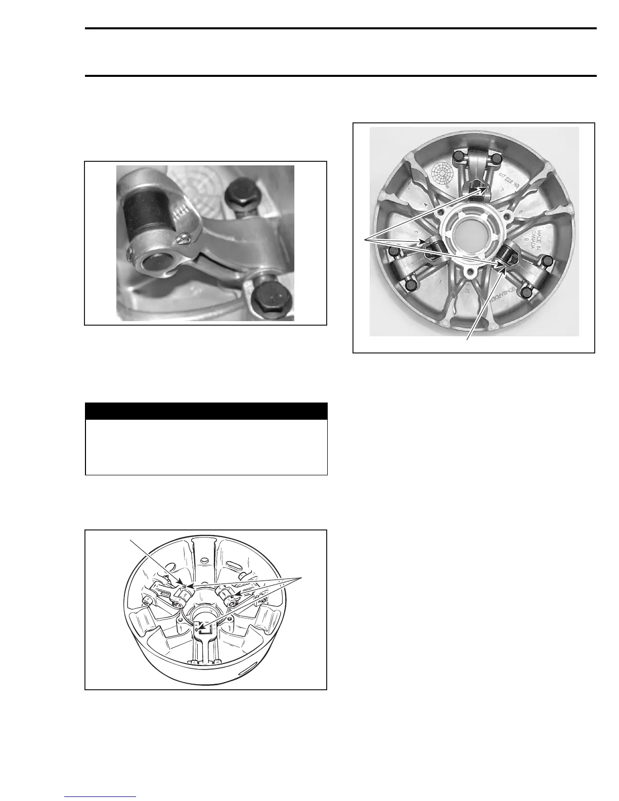
593 /HO/SDI Engine Equipped Models Only
1
2
A32D1XA
1. Head on top
2. All on the same side
All Models
Torque screws no. 19 as per the exploded view.
CAUTION: Lever ass’y and rollers must move
easily after installation.
Fixed Half, Sliding Half, Spring
and Spring Cover
To install spring cover, use spring compressor
(P/N 529 035 524).
Assemble fixed and sliding halves. Note that fixed
halves have different taper angle. Match taper an-
gle with crankshaft.
Lift sliding half against spring cover and align
spring cover arrow with sliding half mark.
mmr2005-087 335