Section 08 DRIVE SYSTEM
Subsection 02 (DRIVE PULLEY)
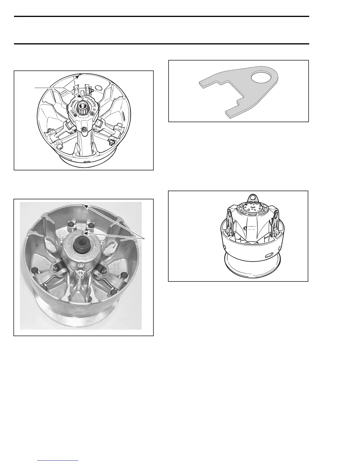
793 HO Engine Equipped Models
A16D0DA
1
TYPICAL
1. Align
593/HO/SDI Engine Equipped Models Only
1
A32D1YA
1. Align
All Models
Tighten screws no. 11 to proper torque as men-
tioned in exploded view.
Sliding Half, Slider Shoe and
Governor Cup
To install governor cup, use the slider shoe fork
(P/N 529 005 500) following tool:
A16B01A
529 005 500
Insert spring no. 31 and slider shoes no. 9 into
governor cup no. 7 so that groove in each slider
shoe is vertical to properly slide in guides.
CAUTION: Make sure O-rings are installed on
slider shoes.
Install a slider shoe fork into slider shoe grooves to
maintain them for governor cup installation. Pro-
ceed on 3 set of slider shoes.
A16B02A
529 005 500
TYPICAL
Make sure to align governor cup arrow with sliding
half and fixed half mark.
NOTE: If fixed half has no mark, align governor
cup mark with segment no. 1 of inner half.Seg-
ments are identified on engine side.
336 mmr2005-087