Section 13 WIRING DIAGRAM
Subsection 01 (WIRING DIAGRAMS)
1
A32Z05A
MALE CONNECTOR HOUSING — CUT-AWAY
1. Lock
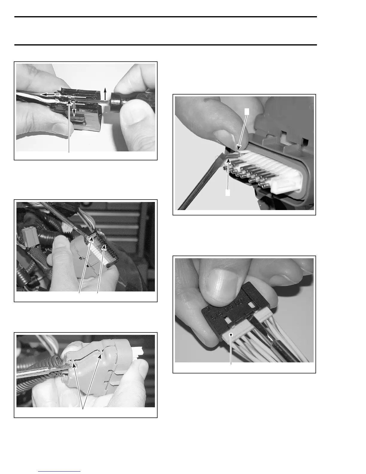
24-Circuit Connector Housing
Push on both tabs to remove retainer.
1
A33Z01A
2
1. Retainer
2. Tab (one on each side)
Open housing by lifting 4 tabs.
1
A33Z02A
1. Tabs (2 on each side)
Lift the top plastic lock of the female terminal to
be removed and hold in position. Lift the female
terminal to unlock from the housing and push out
of housing.
A32E3XA
2
1
1. Lift and hold plastic lock
2. Lift to unlock and push out
8-Circuit Connector Housing
Pry housing to release lock.
1
A33Z04A
1. Lock
Insert tool AMP-755430-2 under tab and pry it to
free connector. Pull on the female terminal wire
to remove female terminal from housing.
492 mmr2005-102