Section 03 ENGINES
Subsection 03 (ENGINE REMOVAL AND INSTALLATION)
A33C4EA
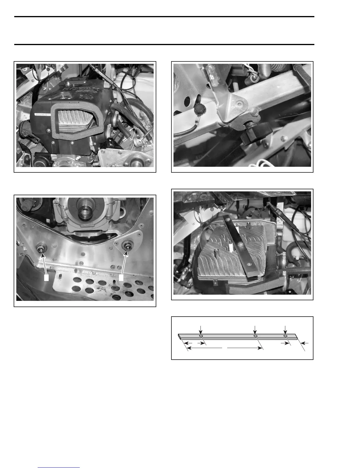
Remove the engine support bolts no. 11 and
no. 12.
A33C4FA
12
1. Rear engine support bolt
2. Front engine support bolt
Remove headlamp adjusting knob from its sup-
port.
A33C4GA
Install the homemade lifting tool.
A33C4HA
Use the following illustration to make the tool.
A33B0TB
C
D D D
B
A
FLAT BAR 152 X 25.4 X 13 MM (16 X 1 X 1/2 IN)
A. 51 mm (2 in)
B. 260 mm (10–1/4 in)
C. 38 mm (1–1/2 in)
D. Diameter: 13 mm (1/2 in)
Lift up the engine.
Unscrew the nuts no. 13 retaining engine support
no. 14 to engine.
62 mmr2005-070