Basic Procedures
40 / 86 H171804E_14_001
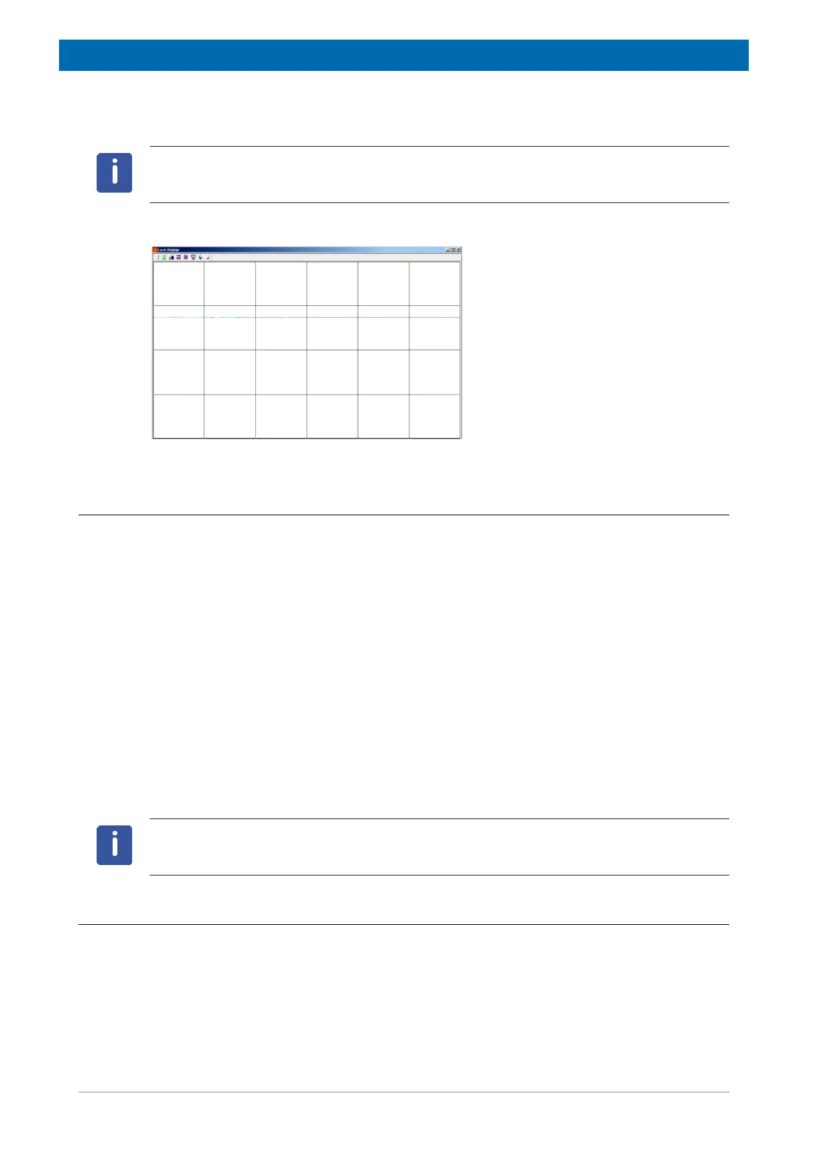
Note: If lock has been achieved, the signal should be of the form of a horizontal line with
some associated noise or ripples (see figure below). The height of this line is called the lock
level.
Figure5.3: Lock Display after Locking the Sample
5.4 Tuning and Matching the Probe
The sensitivity of any probe will vary with the frequency of the signal transmitted to it and
there exists a frequency at which the probe is most sensitive. Furthermore this frequency
may be adjusted over a certain range using tuning capacitors built into the probe circuitry.
Tuning involves adjusting the probe circuitry so that the frequency at which it is most
sensitive is the relevant transmission frequency (SFO1, SFO2 etc.) Each coil in the probe will
be tuned (and matched) separately. If the probe has been changed or the transmission
frequency altered significantly, it may be necessary to retune the probe. For routine work in
organic solvents with selective probes, the value of the transmitted frequencies are unlikely to
vary greatly. Hence, once the probe has been initially tuned, slight variations in frequency will
not warrant retuning. Typically the transmitted frequency would need to be altered by at least
100kHz to warrant retuning. However for broadband probes the frequencies transmitted will
vary greatly from nucleus to nucleus and so the probe will need to be tuned each time the
selected nucleus is altered. Whenever a probe is tuned it should also be matched. Matching
involves ensuring that the maximum amount of the power arriving at the probe base is
transmitted up to the coil which lies towards the top of the probe. This ensures that the
minimum amount of the power arriving at the probe base is reflected back towards the
amplifiers (and consequently wasted).
Note: Bruker offers two different types of tuning and matching adjustments. In addition to the
manual adjustments of the tuning and matching capacitors, the probes can be equipped with
an Automatic Tuning Module (ATM). Follow the steps below for either option.
5.4.1 Probes Equipped with ATM using the Automated Tuning Routine
• On the Workflow button bar, click Tune.
The display will switch automatically to the acquisition window and display the wobble curve.
The tuning and matching is performed automatically. If multiple frequencies are used in a
parameter set such as C13CPD etc., ATMA will start adjusting the lowest frequency first and
will switch in the order of increasing frequency automatically.

 Loading...