EasyManuals Logo

Bruker DektakXT User Manual

Bruker DektakXT
83 pages
To Next Page IconTo Next Page
To Previous Page IconTo Previous Page
Page #20 background imageLoading...
Page #20 background image
System Overview 2-5
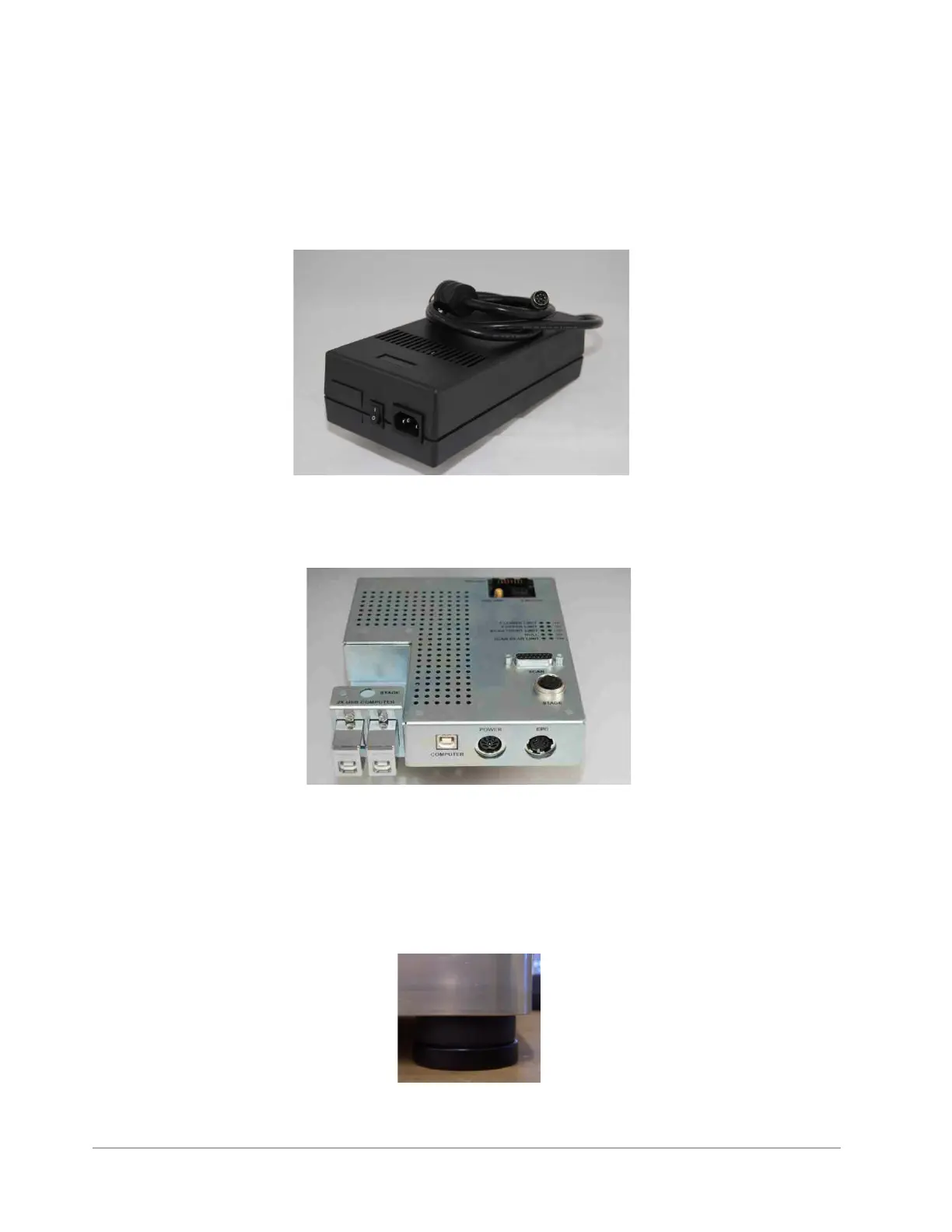
A signal processor provides monitoring and control of the LVDT signal, stylus force coil,
stage motor, and LED illumination (see Figure 2-6). An integrated cable connector panel
handles system input, output, and power signals.
Power demand is 110 VA maximum with a standard outlet power connection.
Figure 2-5: Power Supply Adapter
Figure 2-6: Signal Processor
Base Feet
The standard urethane polymer base feet (see Figure 2-7) help isolate the system from the
surrounding vibrational environment.
Figure 2-7: Standard Base Foot

Table of Contents

Other manuals for Bruker DektakXT

Questions and Answers:

Question and Answer IconNeed help?

Do you have a question about the Bruker DektakXT and is the answer not in the manual?

Bruker DektakXT Specifications

General IconGeneral
BrandBruker
ModelDektakXT
CategoryLaboratory Equipment
LanguageEnglish

Related product manuals