4-4 Taking Measurements and Analyzing Data
NOTE – For instructions on making the settings on the Advanced Tab, see Creating an
Automation Recipe that Includes Deskew Points on page 4-10. For instructions on making the
settings on the Data Stitching and 3D Map tabs, see your Vision64 online Help.
TAKING A STANDARD MANUAL 2D MEASUREMENT
The most common measurement performed on the DektakXT system is a Standard manual 2D
measurement, which consists of a single trace along the sample in the Y direction (that is, along the
front-to-back axis). When the scan is complete, Vision64 provides an output of the two-dimensional
trace, describing the height of surface features with an interactive Z versus Y plot.
The length of the trace that you can define depends upon the DektakXT stage that is installed. For a
DektakXT system with the manual 150mm X-Y stage, the standard scan length can range from 50um
minimum to 55mm maximum. For a DektakXT system equipped with an automated 150mm XY
stage, the standard scan length can range from 50um minimum to 200mm maximum. Scan lengths
from 55mm to 200mm use the DektakXT's data stitching capability, which is described in the online
Help.
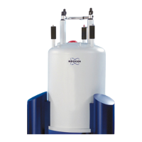
IMPORTANT! Always operate the DektakXT inside its acrylic environmental enclosure
(see Figure 4-1). This enclosure protects the sample and scan area from adverse outside
influences such as noise, vibrations, dust, and air currents. Always operate the system with
the enclosure door closed.
1 In the Vision64 Measurement Setup window, do one of the following:
• If your system includes the X-Y or theta auto stage, click Unload Sample in the Live Video Display.
The tower moves to its full upward position, and the stage moves to its full front (unload) position.
• If your system includes the manual X-Y stage, click Tower Up in the Live Video Display and then
use the manual stage controls to bring the stage to its full front position. For instructions, see Chapter 3.
2 Place the sample on the sample fixture (chuck). If you are measuring a wafer, this will be the vacuum wafer
chuck. If your are measuring a solar sample, this will be the solar chuck. Otherwise, place the sample on
the square base platform of the scan stage itself.
3 If your system includes a vacuum chuck, turn on the vacuum switch.
4 In the Live Video Display, click the Load Sample button . The scan stage moves back to its home
position, ready for a measurement.
WARNING
Always raise the tower prior to loading a sample. Failure to do so can
damage the stylus and sample.