8630 - 121
PROFIBUS DP
Process value (circular plug M 8)
Inductive proximity switches (circular socket M 8)
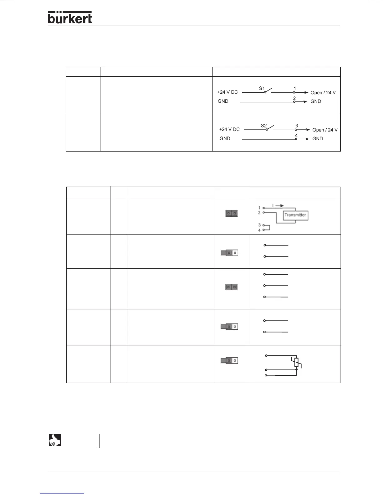
Pin Allocation Signal level
1 Proximity switch 1 + (NO)
2 Proximity switch 1 GND
3 Proximity switch 2 + (NO)
4 Proximity switch 2 GND
Input type * Pin Assignment Jumper** external circuit
4 ... 20 mA 1 + 24 V input transmitter
- internally 2 output transmitter
supplied 3 GND
4 bridge after GND
4 ... 20 mA 1 not assigned
- externally 2 process actual +
supplied 3 not assigned
4 process actual -
Frequency 1 + 24 V - sensor supply
- internally 2 clock input +
supplied 3 clock input - (GND)
4 not assigned
Frequenz 1 not assigned
- externally 2 clock input +
supplied 3 clock input -
4 not assigned
Pt-100 1 not assigned
(see 2 process actual 1 (current supply)
Note 3 process actual 3 (GND)
below) 4 process actual 2 (compensation)
2
4
Pt 100
*
Adjustable via software (see chapter
Procedure for determining the basic settings
)
**
The jumper is located on the connector board of the TOP Control Continuous.
clock +
clock -
clock +
clock -
3
2
1
+24 V
2
3
3
For line compensation reasons, connect sensor Pt-100 via 3 conductors, PIN 3 and PIN 4
must be bridged at the sensor.
NOTE
4
2
+(4..20 mA)
GND